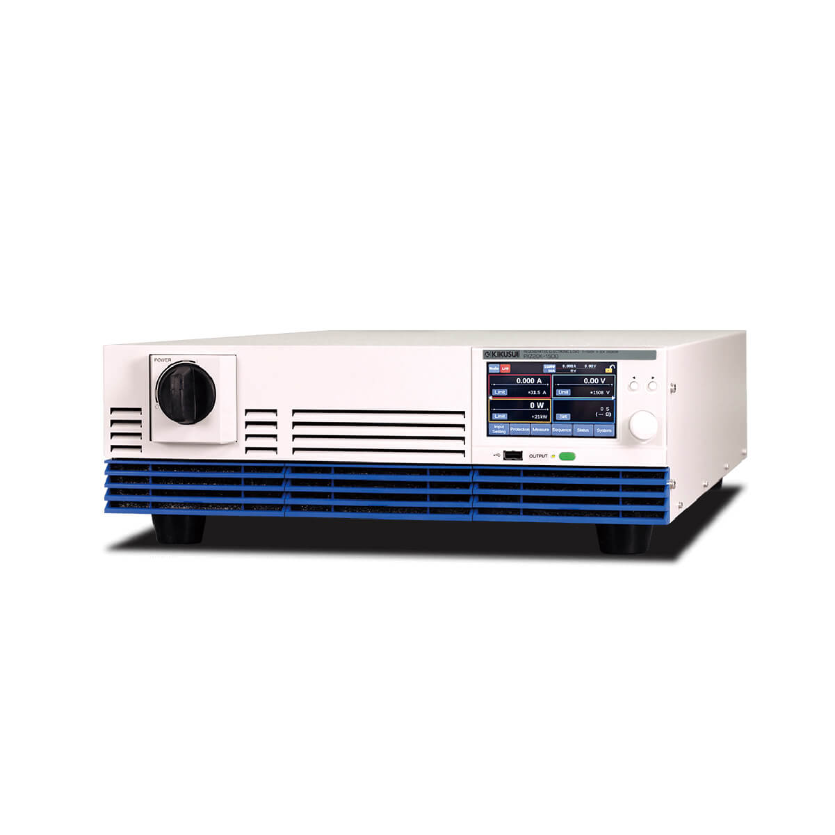


High-Capacity Regenerative Electronic Loads
PXZ Series – 20kW Type
3,100,000円
- 20kW rated power in 3U
- Maximum operating voltage of 1500 V
- Operating modes: CC, CR, CV, CP
- Up to 25 units (500 kW) can be operated in parallel
*Please consult with us if you would like to use 10 or more units in Parallel operation. - Equipped with a touch panel display
- Pre-charge function
- I-V characteristic function
- Sequence function
- LAN, USB, RS232C, external analog control (isolated type) as standard
- Regenerative efficiency of over 90% (on-site regeneration)
| Image | SKU | Output Power [W] | Output CV [V] | Output CC [A] | 標準価格 | WEBかんたんお見積り |
|---|---|---|---|---|---|---|
 | PXZ20K-50 | 20kW | 3 to 50 | 800 | 3,100,000円 (税込:3,410,000円) | |
 | PXZ20K-500 | 20kW | 10 V to 500 V | 120 | 3,100,000円 (税込:3,410,000円) | |
| PXZ20K-1000 | 20kW | 20 to 1000 | 60 | 3,100,000円 (税込:3,410,000円) | |
| PXZ20K-1500 | 20kW | 30 V to 1500 V | 30 | 3,100,000円 (税込:3,410,000円) |
Line-up
| Image | SKU | Output Power [W] | Output CV [V] | Output CC [A] | 標準価格 | WEBかんたんお見積り |
|---|---|---|---|---|---|---|
| PXZ20K-50 | 20kW | 3 to 50 | 800 | 3,100,000円 (税込:3,410,000円) | |
| PXZ20K-500 | 20kW | 10 V to 500 V | 120 | 3,100,000円 (税込:3,410,000円) | |
| PXZ20K-1000 | 20kW | 20 to 1000 | 60 | 3,100,000円 (税込:3,410,000円) | |
| PXZ20K-1500 | 20kW | 30 V to 1500 V | 30 | 3,100,000円 (税込:3,410,000円) |
Specifications
Rating
| Item | PXZ20K-50 | PXZ20K-500 | PXZ20K-1000 | PXZ20K-1500 |
|---|---|---|---|---|
| Rated power | 20000W | |||
| Rated voltage (DC)*1 | 3V to 50V | 10 V to 500V | 20V to 1000V | 30 V to 1500 V |
| Rated current *1 | 800A | 120A | 60A | 30A |
*1 Maximum input current and maximum input voltage are limited by maximum input power.
Constant voltage (CV) mode
| Item | PXZ20K-50 | PXZ20K-500 | PXZ20K-1000 | PXZ20K-1500 |
|---|---|---|---|---|
| Maximum settable voltage | 52.5V | 525V | 1050V | 1575V |
| Setting accuracy | ±(0.2 % of setting + 0.1 % of rating) | |||
| Resolution | 0.005V | 0.05V | 0.1V | 0.1V |
| Remote sensing Maximum compensation voltage (reciprocating) (TYP) | 10% of rating | |||
| Response switching | FAST, SLOW | |||
| Slew rate switching (TYP) | 12.5V/ms or more*1 | 125V/ms or more*1 | 250V/ms or more*1 | 375V/ms or more*1 |
| 12.5V/ms | 125V/ms | 250V/ms | 375V/ms | |
| 1.25V/ms | 12.5V/ms | 25V/ms | 37.5V/ms | |
| 0.125V/ms | 1.25V/ms | 2.5V/ms | 3.75V/ms | |
| 0.0125V/ms | 0.125V/ms | 0.25V/ms | 0.375V/ms | |
*1 MAX will appear on the display.
Constant Current (CC) mode
| Item | PXZ20K-50 | PXZ20K-500 | PXZ20K-1000 | PXZ20K-1500 |
|---|---|---|---|---|
| Maximum settable current *1 | +840A | +126 A | +63A | +31.5 A |
| Setting accuracy*2 | ±(0.75 % of rating) | |||
| Resolution | 0.1A | 0.01A | 0.005A | 0.002 A |
| Line regulation *3 | ±1600mA | ±240 mA | ±120mA | ±60 mA |
| Load regulation *4 | ±1600mA | ±240 mA | ±120mA | ±60 mA |
| Rise time(TYP)*5 | 1 ms | |||
| Fall time(TYP)*6 | 1 ms | |||
| Response switching | FAST, SLOW | |||
| Slew rate switching *1 | 800A/ms or more*7 | 120A/ms or more *7 | 60A/ms or more *7 | 30A/ms or more *7 |
| 400A/ms | 60 A/ms | 30 A/ms | 15 A/ms | |
| 200A/ms | 30 A/ms | 15.0A/ms | 7.5 A/ms | |
| 20A/ms | 3 A/ms | 1.50A/ms | 0.75 A/ms | |
| 2A/ms | 0.30A/ms | 0.150A/ms | 0.075 A/ms | |
*1. During parallel operation, this will be the value multiplied by the number of units in the configuration. *2. Applies to a range of 1 % to 100 % of the rated current. *3. 180 Vac to 252 Vac for 200 Vac input, 342 Vac to 504 Vac for 400 Vac input. At the constant load. *4. This is the amount of change when the voltage is changed from the rated voltage and rated power to 1/10 of the rated voltage. *5. In the case that the CC mode response setting is set to FAST. The time required for the input current in CC mode to change from 10 % to 90 % of the rated current when the input current
value is changed from 0 % to 100 % of the rated current. When the slew rate is set to MAX. *6. In the case that the CC mode response setting is set to FAST. The time required for the input current in CC mode to change from 90 % to 10 % of the rated current when the input current
value is changed from 100 % to 0 % of the rated current. When the slew rate is set to MAX. *7. MAX will appear on the display.
Constant resistance (CR) mode
| Item | PXZ20K-50 | PXZ20K-500 | PXZ20K-1000 | PXZ20K-1500 |
|---|---|---|---|---|
| Conductance rating | 160S | 2400.0 mS | 600.000mS | 200.000 mS |
| Setting range | 0S to 168S | 0 mS to 2520.0 mS | 0mS to 630.000mS | 0 ms to 210.000 mS |
| Setting accuracy*1 | ±(0.5 % of setting + 0.5 % of rating) | |||
| Resolution | 20mS | 0.20 mS | 0.05mS | 0.02 mS |
| Response switching | FAST, SLOW | |||
*1 Converted value at the input current.
Constant Power (CP) mode
| Item | PXZ20K-50 | PXZ20K-500 | PXZ20K-1000 | PXZ20K-1500 |
|---|---|---|---|---|
| Maximum settable power*1 | 21000W | |||
| Setting accuracy*2 | ±(0.5 % of power rating + 0.5 % of current rating × Vin) | |||
| Resolution | 2W | |||
*1 During parallel operation, this will be the value multiplied by the number of units in the configuration. *2 Applies to a range of 5 % to 100 % of the rated power. Rating indicates the rated current value.
200 V three-phase three-wire input
Specifications for models having an input voltage rating of 200 Vac.
| Item | Common to all models |
|---|---|
| Nominal AC input rating | 200 Vac to 240 Vac, 50 Hz to 60 Hz |
| AC Input voltage range | 180 Vac to 252 Vac |
| AC Input frequency range | 47Hz to 63Hz |
| AC Input current (MAX)*1 | 80 A (When Input voltage is 180 V) |
| AC Input power (MAX)*1 | 22 kVA |
| Inrush current (TYP)*2 | 90 A |
| Power factor (TYP)*1 | 0.96 |
| Input hold time | 10 ms or more |
*1 At the rated input power for the rated input current. *2 Maximum peak current value when the POWER switch is turned on. (Excluding the surge current to the input filter capacitor.)
400 V three-phase three-wire input
Specifications for models having an input voltage rating of 400 Vac.
| Item | Common to all models |
|---|---|
| Nominal AC input rating | 380 Vac to 480 Vac, 50 Hz to 60 Hz |
| AC Input voltage range | 342 Vac to 504 Vac |
| AC Input frequency range | 47Hz to 63Hz |
| AC Input current (MAX)*1 | 40 A (When Input voltage is 342 V) |
| AC Input power (MAX)*1 | 22 kVA |
| Inrush current (TYP)*2 | 70 A |
| Power factor (TYP)*1 | 0.96 |
| Input hold time | 10 ms or more |
*1 At the rated input power for the rated input current. *2 Maximum peak current value when the POWER switch is turned on. (Excluding the surge current to the input filter capacitor.)
Display
| Item | PXZ20K-50 | PXZ20K-500 | PXZ20K-1000 | PXZ20K-1500 | |
|---|---|---|---|---|---|
| Voltmeter | Maximum display | ±60.000V | ±600.00 V | ±1200.00V | ±1800.00 V |
| Display accuracy | ±(0.1 % of reading + 0.2 % of rating) | ||||
| Ammeter | Maximum display | ±1120.000A | ±168.000 A | ±84.000A | ±42.000 A |
| Display accuracy | ±(0.75 % of rating) | ||||
| Wattmeter | Maximum display*1 | ±24.000 kW | |||
| Display accuracy | Display the integrated value of voltmeter and ammeter | ||||
| Operation display | Load ON / OFF | The LOAD LED on the front panel lights in green | |||
| Operation mode | Indicate the followings on the upper left part of the display CV: CV icon CC: CC icon CR: CR icon CP: CP icon | ||||
| Remote (LAN) | Indicate the followings on the upper left part of the display | ||||
| Alarm | Indicate the details of activated protection function on the display | ||||
| SCPI error | Indicate the error occurring at present on the display | ||||
| POWER off | Indicate residual charge warning and an instruction to turn off the display, then reboot | ||||
| key lock | Indicate the key lock status on the upper right part of the display | ||||
| Sensing | When sensing is enabled, indicate the sensing icon on the upper right part of the display | ||||
| During parallel operation | Displaying the slave state on the slave unit | ||||
| External control | When digital input/output is enabled, indicate the EXT icon on the upper right part of the display | ||||
*1 The unit will be W if it is less than 10 kW.
Protection specifications LOW alarm
An alarm not requiring a reboot to be cleared.
| Item | PXZ20K-50 | PXZ20K-500 | PXZ20K-1000 | PXZ20K-1500 | |
|---|---|---|---|---|---|
| OVP (Over Voltage Protection) | Protective operation | Load off, indicate “OVP” on the display. SLV OVP is displayed on the slave unit. | |||
| Setting range | 5V to 60V | 50 V to 550 V | 100V to 1100V | 150 V to 1650 V | |
| Setting accuracy | ±(0.1 % of setting + 0.2 % of rating) | ||||
| Resolution | 0.005V | 0.05V | 0.1V | 0.1V | |
| OCP (Over Current Protection) | Protective operation | Load off, indicate “OCP” on the display. SLV OCP is displayed on the slave unit. | |||
| Setting range*1 | 80A to 880A | 12 A to 132 A | 6A to 66A | 3 A to 33 A | |
| Setting accuracy | ±(0.75 % of rating) | ||||
| Resolution | 0.1A | 0.01A | 0.005A | 0.002 A | |
| OPP (Over Power Protection) | Protective operation | Load off, indicate “OPP” on the display. SLV OPP is displayed on the slave unit. | |||
| Setting range*1 | 2 kW to 24 kW | ||||
| Setting accuracy | ±(1.0 % of power rating + 1.0 % of current rating × Vin) | ||||
| Resolution | 2W | ||||
| UVP (Under Voltage Protection) | Protective operation | Load off, indicate “UVP” on the display. SLV UVP is displayed on the slave unit. | |||
| Setting range | 0V to 50V | 0 V to 500 V | 0V to 1000V | 0 V to 1500 V | |
| Selectable | Enable/Disable | ||||
| Setting accuracy | ±(0.1 % of setting + 0.2 % of rating) | ||||
| Resolution | 0.005V | 0.05V | 0.1V | 0.1V | |
| Watchdog Alarm (Communication error protection) | Protective operation | Load off, indicate “WDOG” on the display | |||
| Setting range | 1 s to 3600 s | ||||
| Selectable | Enable/Disable | ||||
| External Alarm LOW Level (external input alarm detection) | Protective operation | Load off, indicate “EXT LOW” on the display | |||
*1 During parallel operation, this will be the value multiplied by the number of units in the configuration.
Protection Specifications HIGH alarm
An alarm requiring a reboot to be cleared.
| Item | Common to all models | |
|---|---|---|
| Reverse Alarm (Reverse-connection detection protection) | Protective operation | Load off, indicate “REVE” on the display |
| OHP (Overheat protection) | Protective operation | Load off, indicate “OHP” on the display. SLV OHP is displayed on the slave unit. |
| Line OVP (Grid overvoltage protection) | Protective operation | Load off, indicate “LOVP” on the display. SLV LOVP is displayed on the slave unit. |
| Setting range | Input voltage rating 200 Vac model: 200 V to 258 V Input voltage rating 400 Vac model: 380 V to 516 V | |
| Line UVP (Grid undervoltage protection) | Protective operation | Load off, indicate “LUVP” on the display. SLV LUVP is displayed on the slave unit. |
| Setting range | Input voltage rating 200 Vac model: 175 V or less. Input voltage rating 400 Vac model: 333 V or less. | |
| Line Frequency Error (Grid abnormal frequency protection) | Protective operation | Load off, indicate “FREQ” on the display. SLV FREQ is displayed on the slave unit. |
| Detection value | 42 Hz/68 Hz | |
| External Alarm HIGH Level (External input alarm detection) | Protective operation | Load off, indicate “EXT HIGH” on the display |
| SENS Alarm (incorrect sensing connection detection) | Protective operation | Load off, indicate “SENS” on the display |
| Setting range | Enable/Disable | |
| Parallel Communication Error (Parallel operation communication error detected) | Protective operation | Load off, indicate “PARA COM” on the display |
| Para Other Slave Alarm (Parallel operation slave error occurred) | Protective operation | Load off, indicate “SLV OTHR” on the display |
| Incorrect Slave Alarm (Not applicable device connected) | Protective operation | Load off, indicate “SLV INC” on the display |
| Too many connections (Too many parallel connections) | Protective operation | Load off, indicate “TOO MANY” on the display |
| Hardware ERR*1 (Hardware error) | Protective operation | Load off, indicate “ERRH” on the display. SLV ERRH is displayed on the slave unit. |
| Software ERR*2 (Software error) | Protective operation | Load off, indicate “ERRS” on the display. SLV ERRS is displayed on the slave unit. |
*1 It occurs when an abnormality related to the software is detected and the internal unit comes to an emergency stop. *2 It occurs when an abnormality related to the software is detected and the internal unit comes to an emergency stop.
External analog I/O
| Item | Common to all models | ||
|---|---|---|---|
| Input | Input points | 2 points | |
| Voltage (CV) control | Setting range | 0 % to 100 % of the rated voltage | |
| Input voltage range | 0 V to 5 V or 0 V to 10 V (Selectable) | ||
| Accuracy | ±(1 % of rating) | ||
| Current (CC) control Power (CP) control Resistance (CR) control*1 | Setting range | 0 % to 100 % of the rated current, rated power and rated conductance | |
| Input voltage range | 0 V to 5 V or 0 V to 10 V (Selectable) | ||
| Accuracy | ±(1 % of rating) | ||
| Output | Output points | 2 points | |
| Voltage monitor (VMON) | Monitor range | 0 % to 100 % of the rated voltage | |
| Output voltage range | 0 V to 5 V or 0 V to 10 V (Selectable) | ||
| Accuracy | ±(1 % of rating) | ||
| Current monitor (IMON) | Monitor range | 0 % to 100 % of the rated current | |
| Output voltage range | 0 V to 5 V or 0 V to 10 V (Selectable) | ||
| Accuracy | ±(1 % of rating) | ||
*1 Select either current control or power control.
External digital input
| Item | Common to all models | |
|---|---|---|
| Fixed input points | 1 point (Polarity switchable) | |
| Selected input points | 5 points (Polarity switchable) | |
| Input form | Photocoupler isolated input (Applicable to both current sink / source output) | |
| Fixed function | ALARM IN | HIGH alarm occurrence |
| Selecting function | OFF | Do not use terminals |
| LOAD ON | Turn on the load | |
| LOAD OFF | Turn off the load | |
| LOAD CTRL | Turn on of off the load | |
| L ALARM IN | LOW alarm occurrence | |
| ALARM CLR | LOW alarm clearance | |
| SEQ RUN | Sequence start/end | |
| SEQ PAUSE | Sequence pause/resume | |
| SEQ TRIG IN | Input the trigger for sequence | |
| ACQUIRE TRIG | Input the measurement trigger | |
| MEM1 RECALL | Recall preset memory 1 | |
| MEM2 RECALL | Recall preset memory 2 | |
| INTEG CTRL | Starting/stopping integration measurement | |
| INTEG RESET | Resetting integration measurement data | |
| External circuit power supply range | 12 V to 24 Vdc (±10 %) | |
External digital output
| Item | Common to all models | |
|---|---|---|
| Output points | 6 points (Polarity switchable) | |
| Output form | Semiconductor relay output | |
| Selecting function | OFF | Do not use terminals |
| LOAD ON | Outputs a signal when load is turned on | |
| POWER ON | Signal is output when power supply is on and load is possible | |
| H ALARM OUT | Output a signal when a HIGH alarm occurs | |
| L ALARM OUT | Output a signal when a LOW alarm occurs | |
| CC STATUS | Output a signal when operating in the CC mode | |
| CV STATUS | Output a signal when operating in the CV mode | |
| SEQ TRIG OUT | Output the trigger for sequence | |
| SEQ STATUS | Signal is output while the sequence is running | |
| EXT DIN BUSY | Output a signal when the digital input is in BUSY status | |
| MEM1 ACT TIME | Signal is output when the setting is completed for preset memory 1 | |
| MEM2 ACT TIME | Signal is output when the setting is completed for preset memory 2 | |
| RELAY DRIVE | Links with load on/off and outputs a signal with a time difference of approx. 100 ms. You can set this parameter to only Ch.6. | |
Communication interface
| Item | Common to all models | |
|---|---|---|
| Common specifications | Software protocol | IEEE std. 488.2-1992 |
| Command language | Complies with SCPI Specification 1999.0 | |
| RS232C | Hardware | D-SUB 9-pin connector Baud rate: 1200, 2400, 4800, 9600, 19200, 38400, 57600, 115200 bps Data length: 8 bits, Stop bits: 1 bit, Parity bit: None Flow control: No, CTS-RTS |
| Program message terminator | LF during reception, LF during transmission. | |
| USB (device) | Hardware | Standard type B socket. Complies with the USB 2.0 specifications; data rate: 480 Mbps (high speed) |
| Program message terminator | LF or EOM during reception, LF + EOM during transmission | |
| Device class | Conforms to USBTMC-USB488 device class specifications. | |
| USB (host) | Hardware | Standard type A socket. Complies with the USB 2.0 specifications; data rate: 480 Mbps (high speed) |
| LAN | Hardware | IEEE 802.3 100BASE-TX or 10BASE-T Ethernet |
| Communication protocol | SCPI-RAW, SCPI-Telnet, HiSLIP, VXI-11 | |
| Program message terminator | HiSLIP: LF or END during reception, LF + END during transmission. SCPI-RAW: LF during reception, LF during transmission | |
| Compliant standards | LXI Version 1.5 Specifications 2016 | |
Others
| Item | Common to all models | ||
|---|---|---|---|
| Synchronization function (clock synchronization) | Overview | SYNC icon is displayed on the display when synchronization is established with the internal clock after connecting with other PXZ series using the EXT SYNC connector. | |
| Sequence synchronization | Synchronization of the program start and step start. | ||
| Measurement synchronization | Synchronization of the measurement start | ||
| Load synchronization | Synchronization of load ON/OFF | ||
| Sequence function | Operation mode | CV, CC, CR and CP modes | |
| Maximum number of programs | 30 | ||
| Maximum number of steps | 10000 | ||
| Step execution time | 1 ms to 3600000 s | ||
| Loop count | 1 to 100000, or infinite | ||
| Sine Function | Operation mode | CV/CC mode | |
| Frequency setting range | 1 Hz to 1000 Hz | ||
| Frequency precision setting | 1 Hz to 10 Hz | 0.2Hz | |
| 12 Hz to 100 Hz | 2Hz | ||
| 120 Hz to 1000 Hz | 20Hz | ||
| CV | Maximum setting | Setting range up to 105 % of rated voltage | |
| Maximum offset setting | |||
| CC | Maximum setting | Setting range up to 105 % of rated current | |
| Maximum offset setting | |||
| Pulse function | Operation mode | CV/CC/CR mode | |
| Frequency setting range | 1 Hz to 1000 Hz | ||
| Frequency precision setting | 1 Hz to 10 Hz | 0.01Hz | |
| 12 Hz to 100 Hz | 0.1Hz | ||
| 120 Hz to 1000 Hz | 1Hz | ||
| CV | High level | Setting range up to 105 % of rated voltage | |
| Low level | |||
| CC | High level | Setting range up to 105 % of rated current | |
| Low level | |||
| CR | High level | Setting range up to 105 % of rated conductance | |
| Low level | |||
| Duty cycle | 2.5 % to 97.5 % | ||
| Over current protection (OCP) delay function | Setting range | 1 ms to 2000 ms | |
| Resolution | 1 ms | ||
| Multichannel (VMCB) function | Connection between the master unit and a PC | LAN, USB, RS232C | |
| Connection with slave units | LAN | ||
| Measurement trigger | Measurement start condition (trigger source) | Conditions for starting measurement can be selected (when inputting from display, when inputting commands by remote control, when inputting signals by external control, when operating in synchronization, and when load off) | |
| Number of measurements | 1 to 65536 | ||
| Measurement delay time | Setting range | 0 s to 100 s | |
| Resolution | 0.1ms | ||
| Measurement interval | Setting range | 0.1 ms to 3600 s | |
| Resolution | 0.1ms | ||
| Measurement time | Setting range | 0.1 ms to 1 s | |
| Resolution | 0.1ms | ||
| I-V characteristic function | Operation mode | CV/CC mode | |
| Number of setup items | 3 to 100 items (interpolated between points with straight lines) | ||
| Preset memory | Number of memory entries | 20 | |
| Saved setting | Values in CV, CC, CP, and CR modes, and protection function values | ||
| Setup Memory | Number of memory entries | 21 | |
| Saved setting | Load on/off, Input voltage value/Input current value/Input power value/Conductance value, Input mode, Response, Slew Rate, Priority operation mode (Priority when load is ON), Value of the pulse function (Duty, Frequency, High, Low), Value of the sine function (Amplitude, Frequency, Offset), Number of I-V characteristics (Count), Over voltage protection (OVP), Under voltage protection (UVP, UVP Enable), Over current protection (OCP, Delay), Over power protection (OPP), Line overvoltage protection (Line OVP), Measurement trigger settings (Source, Count, Delay, Enable, Timer), Integration settings (Gate, Reset) | ||
| key lock | Level 1 | Load on/off and preset memory recall are available | |
| Level 2 | Load on/off are available | ||
| Level 3 | Load off is available | ||
| Number of parallel operated load modules | Up to 25 units *Please contact us if you wish to operate more than 10 units in parallel. | ||
| Pre-charge function*1 | Maximum settable voltage | 105% of voltage rating | |
| Voltage setting accuracy | ±(0.2 % of setting + 0.1 % of rating) | ||
| Current setting accuracy*2 | ±(1.0 % of rating) | ||
*1 Release the interlock. *2 Fixed set value of 5 % of rated current.
General Specifications
| Item | PXZ20K-50 | PXZ20K-500 | PXZ20K-1000 | PXZ20K-1500 | |
|---|---|---|---|---|---|
| Weight | Approx. 41 kg (90.39 lbs) | Approx. 38 kg (83.78 lbs) | Approx. 37 kg (81.57 lbs) | Approx. 37 kg (81.57 lbs) | |
| Dimensions | 430 (16.93)(MAX455 (17.91))W × 128 (5.04)(MAX160 (6.30))H × 720 (28.35)(MAX980 (38.58))D mm (inches) Refer to Outline Drawing | ||||
| Environmental conditions | Operating environment | Indoor use, overvoltage category II | |||
| Operating temperature | 0℃ to +40℃ | 0 °C to +50 °C (32 °F to +122 °F) | |||
| Operating humidity | 20% rh to 85% rh (no condensation) | ||||
| Storage temperature | -25 °C to +60 °C (-13 °F to +140 °F) | ||||
| Storage humidity | 90 % rh or less (no condensation) | ||||
| Altitude | Up to 2000 m | ||||
| Cooling method | Forced air cooling using fan | ||||
| Accessories | AC INPUT terminal cover, External control connector kit (1 set), Chassis connection wire, DC INPUT terminal cover, DC INPUT terminal screws (1 pair), EXT SYNC connector cover, SENSING connector cover, SENSING connector (2 pc.), Synchronized operation signal cable kit, Safety Information (1 copy), China RoHS sheet (1 sheet), Getting Started Guide (1 copy), Heavy object warning label (1 piece) | ||||
| Withstanding voltage | Between primary and FG | 2200 Vac for 1 minute | |||
| Between primary and secondary | |||||
| Between secondary and FG | 500 Vdc for 1 minute | 1800 Vdc for 1 minute | 3000 Vdc for 1 minute | ||
| Insulation resistance | Between primary and FG | 30 MΩ, 500 Vdc | |||
| Between primary and secondary | 30 MΩ, 500 Vdc | 30 MΩ, 1000 Vdc | |||
| Isolation voltage | ±250V | ±1000V | +2000V/-1000V | ||
| Electromagnetic compatibility (EMC)*1*2 | Complies with the requirements of the following directive and standards. EMC Directive 2014/30/EU EN 61326-1 (Class A*3) | ||||
| Safety*1 | Complies with the requirements of the following directive and standards. Low Voltage Directive 2014/35/EU*2 EN 61010-1 (Class I*4, Overvoltage category II, Pollution Degree 2*5) | ||||
*1 Does not apply to specially ordered or modified products. *2 Only for models with CE mark / UKCA mark on their body. *3 This is a Class A instrument. This product is intended for use in an industrial environment. This product may cause interference if used in residential areas. Such use must be avoided unless the user takes special measures to reduce electromagnetic emissions to prevent interference to the reception of radio and television broadcasts. *4 This is a Class I instrument. Be sure to ground this product’s protective conductor terminal. The safety of this product is guaranteed only when the product is properly grounded. *5 Pollution is addition of foreign matter (solid, liquid or gaseous) that may produce a reduction of dielectric strength or surface resistivity. Pollution Degree 2 assumes that only non-conductive pollution will occur except for an occasional temporary conductivity caused by condensation.
Dimensions(mm)

Options
Load cable
*For PXZ20K-50

*For PXZ20K-500
*For PXZ20K-1000, PXZ20K-1500

Three-phase input power cord
Parallel-operation cable
Rack Mount Bracket
GPIB Converter

Catalog
Manual
2D CAD
Updater/Driver

Technical Data