Modular Multifunction Electronic Load
PLZ-U Series
The PLZ-U Series provides a set of compact, high-performance multichannel electronic load systems capable of operating in five modes – constant current, constant resistance, constant voltage, constant current+constant voltage and constant resistance+constant voltage.

Features
The PLZ-U Series provides a set of compact, high-performance multichannel electronic load systems capable of operating in five modes – constant current, constant resistance, constant voltage, constant current+constant voltage and constant resistance+constant voltage.
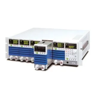
Adopting the modular (plug-in) design, the Series consists of four models – two frame models and two load unit models. The PLZ-30F frame can configure the load units up to three channels, and the PLZ-50F frame can configure up to five channels. Two load unit models are available, the PLZ- 70UA (75-watt load that operates even at 0 V) and PLZ-150U (150-watt load that operates from 1.5 V up).
Since parallel operation of load units is possible, the current and power capacity can be flexibly adjusted according to the output of the device under test — from 75 W up to 750 W (when five PLZ150U units are installed in the PLZ-50F).
Additionally, it features a wide range of functions including high-speed response with a maximum slew rate of 2.4A/μs (PLZ150U) and minimum resolution of 10μA (PLZ70UA), plus soft start function, variable slew rate, switching function, ABC preset memory, 4 setup memories, sequence function, and timer with time/voltage measurement functions that enable battery discharge characteristic evaluation.
GPIB and RS232-C communication functions are standard equipment, making it easy to integrate into various test systems and convenient for testing fuel cells, secondary batteries, DC/DC converters, switching power supplies, and multi-output power supplies. Each interface supports IEEE488.2 as well as SCPI (Standard Commands for Programmable Instruments: common commands designed for test and measurement equipment).
Multi-Channel Load Systems Can Be Built Easily!
Five operation modes
The system is capable of operating in five modes – constant current, constant resistance, constant voltage, constant current + constant voltage and constant resistance + constant voltage.

Variable slew rate
The slew rate determines the slope of change in the current when the set current needs to change sharply as in a transient response test. This system lets you set the current change rate per unit time as appropriate for the selected current range.
| Slew rate | |||
|---|---|---|---|
| PLZ150U | PLZ70UA | ||
| CC mode | H | 0.10A/μs to 2.40A/μs | 0.05A/μs to 1.20A/μs |
| M | 0.10A/μs to 0.24A/μs | 0.05A/μs to 0.12A/μs | |
| L | 24mA/μs* | 12mA/μs* | |
| CR mode | H | 0.10A/μs to 0.24A/μs | 0.05A/μs to 0.12A/μs |
| M | 24mA/μs* | 12mA/μs* | |
| L | 2.4mA/μs* | 1.2mA/μs* | |
| Resolution | 0.01A/μs | ||
*Fixed value
High precision and high resolution
The built-in three-range configuration provides both wide dynamic range and high precision. The voltmeter, ammeter and wattmeter functions that display values using up to five digits each and a minimum set ting resolution of either 10 μA (PLZ70UA) or 20 μA (PLZ150U) are implemented.
| Measurement display resolution | ||
|---|---|---|
| Resolution | ||
| Voltmeter | 15.75V to 150V | 0.01V |
| 0 V to 15.75 V | 0.001V | |
| Ammeter | H | 0.001A |
| M | 0.0001A | |
| L | 0.01mA | |
| Wattmeter | Less than 100 W | 0.01W |
| 100 W or more | 0.1W | |
0-V input
The PLZ70UA model operates even when the input operating voltage is 0 V. This feature is indispensable for testing singlecell fuel cells. The continuing trend toward lower power consumption and semiconductor process miniaturization is driving semiconductor devices to operate with increasingly lower voltages. This makes PLZ70UA suitable for use when evaluating such power supplies.
Diverse load on/off operations
Both load units and frames have LOAD keys on them. The load on/off operations listed below are available. You can choose any of these operations as suitable for your operating environment.
| Load On/Off | |
|---|---|
| Selected channel only | Operation using the LOAD key of the load unit |
| All channels simultaneously | Operation using the LOAD key of the frame |
| Delayed load-on | Turns on the load when the set time elapses after the LOAD key is pressed. |
| Power on load | Turns on the load automatically when the system is powered on. |
| Auto load off timer | Turns off the load when the set time elapses after the load-on operation. |
| External control | Controls the load on/off operations using external signals. |
| Elapsed time display | Displays the time from load on to load off. |
| Load off voltage display | Stores the value of voltage recorded when the load is turned off. |
Parallel operation of units allows for large capacity. *Parallel operation is only available on the same model.
Channel-synchronized operations
You can have all the channels operated in synchronization for the load on/of f, ABC preset memor y, setup memor y and sequence operations, respectively.
| Channel-synchronized operations | |
|---|---|
| Load on/off | Turns on or off the load for all the channels simultaneously. |
| ABC Preset Memories | Calls memory data for all the channels simultaneously. |
| Setup Memory | Saves or calls memory data for all the channels simultaneously. |
| Sequence | Executes or stops sequence programs for all the channels simultaneously. |
Frame control
By connecting two or more frames, you can perform channelsynchronized load on/off, ABC preset memory call and setup memory call operations for all the channels simultaneously while controlling up to four frames from a single frame.

Parallel operation
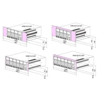
Adjacent load modules of the same model installed in the same frame can be operated in parallel*. Parallel operated load modules are regarded as a single channel, and their total current and resistance (conductance) values are used as displayed and set values. Parallel operated load modules and standalone load modules can coexist in the same frame. *PLZ-50F can accommodate up to five load modules.
 When PLZ-50F houses one set of three parallel operated load modules and another set of two parallel operated load modules
 When PLZ-50F houses one set of three parallel operated load modules and two standalone load modules
| Number of parallel operated load modules and capacities | ||
|---|---|---|
| Number of parallel operated load modules | PLZ70UA | PLZ150U |
| 2 | 30A / 150W | 60A / 300W |
| 3 | 45A / 225W | 90A / 450W |
| 4 | 60A / 300W | 120A / 600W |
| 5 | 75A / 375W | 150A / 750W |
Sequence function
The sequence function automatically executes a stored program step by step in constant current or constant resistance mode. You can set a value and an execution time for each step individually, which enables you to perform simulations with various waveforms. A separate program can be prepared for each channel, and the backup function retains these programs even if the system is powered off.

| Sequence setting parameters | |
|---|---|
| Mode | CC or CR |
| Step execution time | 1 ms to 9999 s (0 = End of the step) |
| Maximum number of steps | 255 |
| Number of repetitions | 0 to 9999 (9999 = Repeated infinitely) |
Elapsed time display and auto load off timer
Combining four functions – elapsed time display, under voltage protection (UVP), load off voltage display and auto load off timer – makes it possible to perform two types of measurements that are useful in battery discharge tests – measurement of the time elapsed from the start of discharge until the final voltage is detected and measurement of the closed circuit voltage after the specified time elapses from the start of discharge.

Switching function
Switching operations can be performed in constant current and constant resistance modes. The switching setting parameters are the switching level, switching frequency, duty factor and slew rate. These parameters can be changed while this mode is in operation.
| Switching setting parameters | ||
|---|---|---|
| Duty factor | 2 % to 98 %, in steps of 0.1 % | |
| Frequency setting range | 1 Hz to 20 kHz | |
| Frequency resolution | 1 Hz to not higher than 1 kHz | 1Hz |
| 1 kHz to not higher than 10 kHz | 10Hz | |
| 10 to 20 kHz | 100Hz | |
Soft start function
The soft start function allows the rise time of the current to be changed after the load-on operation in constant current mode. Since the rise time for the system can be changed according to the output-voltage rise time for the device being tested, you can conduct tests under highly realistic load conditions. (The soft start time can be selected from the following options – 0.1, 1, 3, 5, 10, 30, 100 and 300 ms.)
Remote sensing function
The remote sensing function compensates for voltage drops in load lines. It is used to set resistance and voltage values correctly and to make accurate voltage and power measurements. Particularly, the function improves the transitional characteristics in constant voltage and constant resistance modes, leading to stable operation.
ABC preset memories
Three memories A, B and C are provided for each range in constant current, constant resistance and constant voltage modes, and the set values can be saved. The stored set values can be called freely even while the load is on and saved again. In the constant current + constant voltage and constant resistance + constant voltage modes, the constant current and constant voltage memories and the constant resistance and constant voltage memories can be called and saved, respectively.
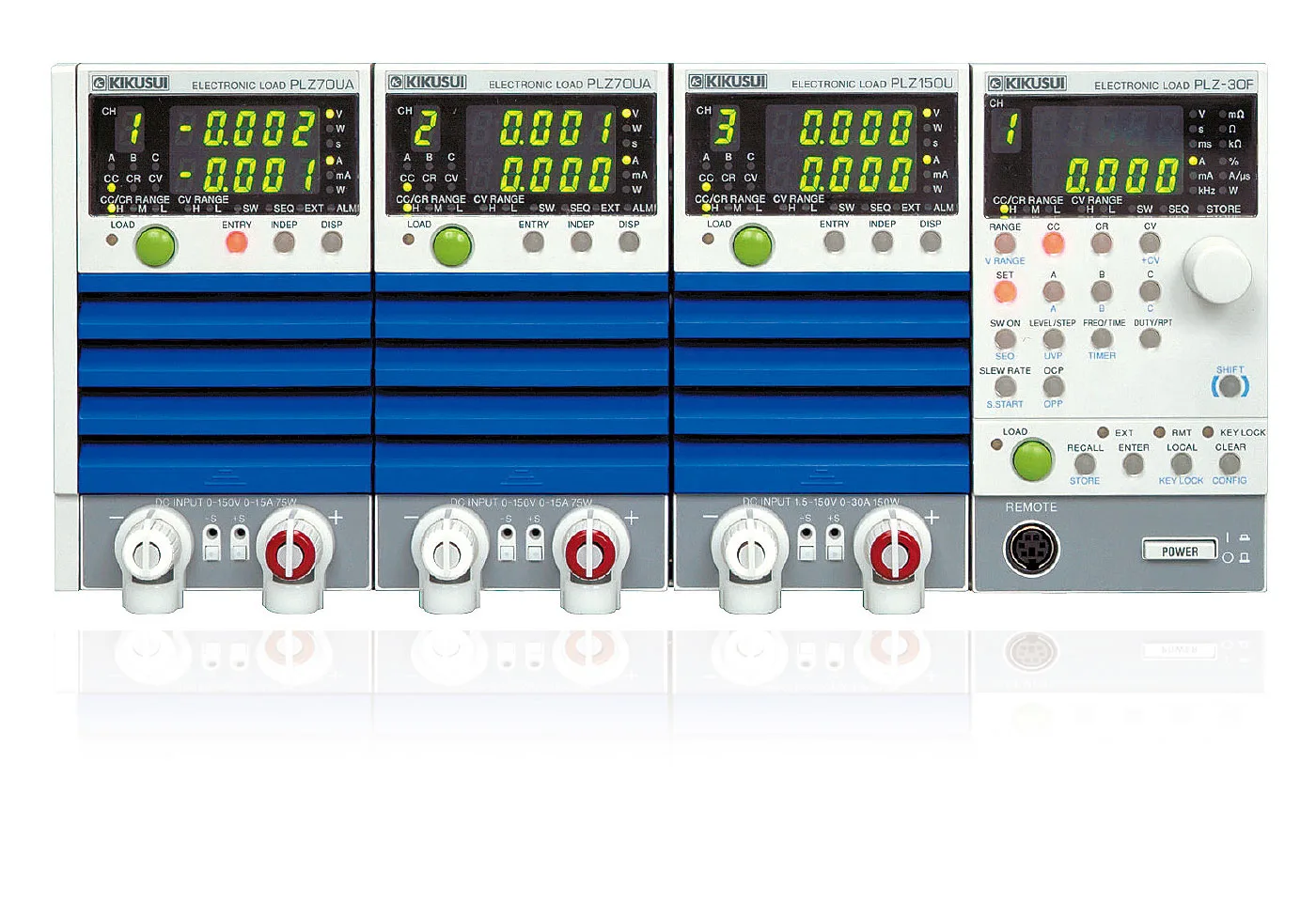
Ease of operation
All the knobs and keys necessary for the setting operations are provided on the frame panel. You can perform the setting operations by one hand while viewing the measured voltage and current values displayed on a channel-by-channel basis. The analog-like rotary knobs, which employ rotation speedsensitive encoders, and intuitive design make the system very easy to operate.
Key lock function
This function locks the panel keys so that the set values, memory data, sequences and other settings cannot be changed.
Numerous protection functions
The system features the following protection functions – over current protection (OCP), over power protection (OPP), overvoltage protection (OVP), under voltage protection (UVP), over heat protection (OHP) and reverse connection protection (RVP). Because the OCP, OPP and UVP values can be changed on a per-channel basis, you can optimize the protection settings for each device to be tested.
Setup Memory
Up to four of the set values listed below can be saved in the setup memories. The set values are called or saved for all the channels simultaneously.
- Operation mode (CC, CR and CV/+CV)
- Current, resistance and voltage values recorded when saved
- Range setting
- Slew rate
- Switching frequency, duty factor and level
- Soft start
- Configuration settings
- ABC preset memory data
- Auto load off timer
- Sequence
Configuration settings
This function configures the settings related to the system operation, communication environment, etc. These settings are stored in the system memory and called when the power is turned on.
- Number of parallel operated load modules
- Operation mode in which the external reference voltage input is used
- Over current protection (OCP) load off function
- Over power protection (OPP) load off function
- Load on delay time
- Load on/off operation at the end of the sequence
- Polarity of load on external control (low/high)
- Load on/off operation at powering on
- Choice between GPIB and RS-232C
- GPIB address setting
- RS-232C communication speed
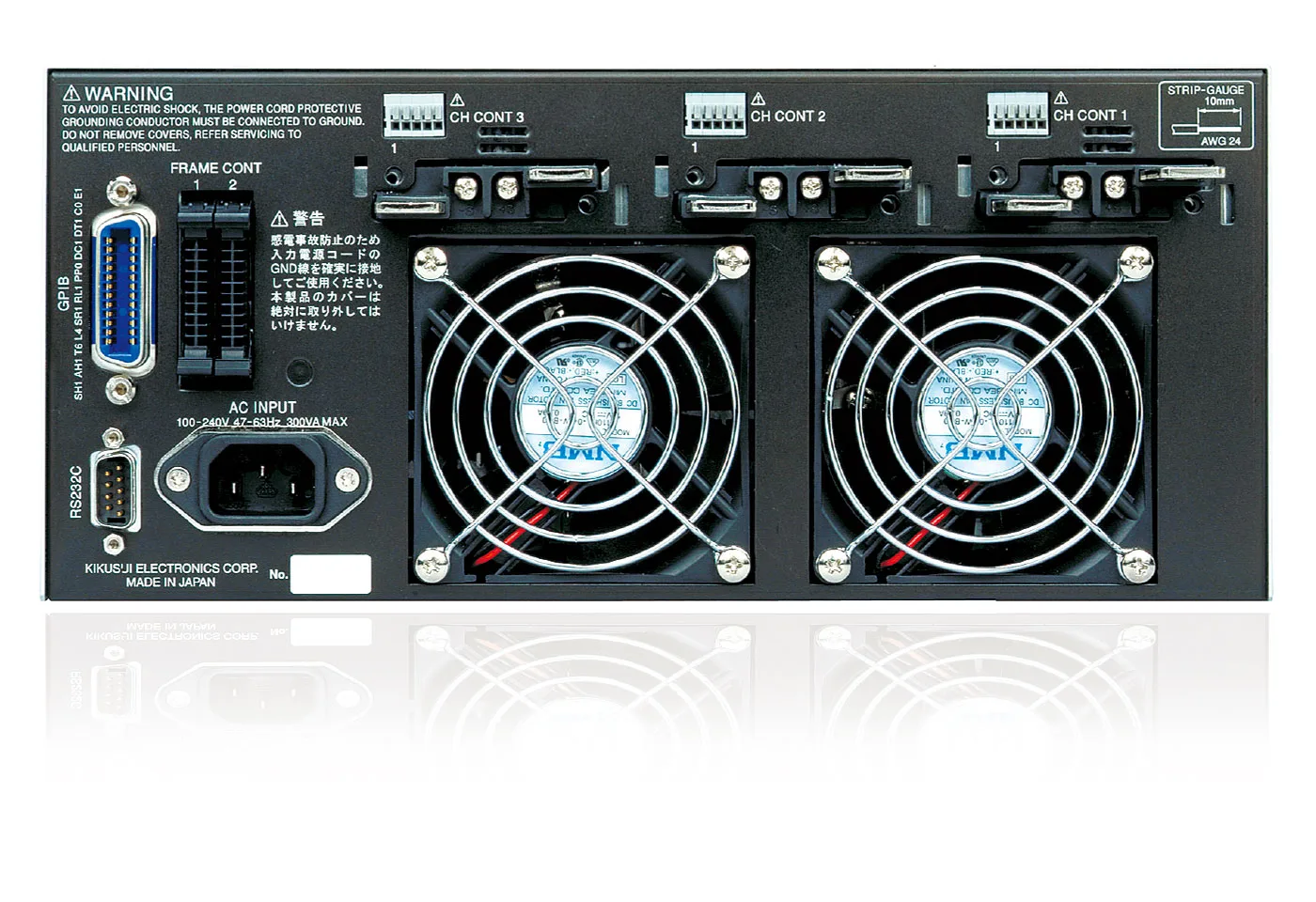
External control
External controls are provided using the frame connector (FRAME CONT) and each channel connector (CH CONT). The frame connector (FRAME CONT) lets you perform the channel-synchronized load on/off, ABC preset memory call, setup memor y call, load status output and alarm status output operations. Also, using the channel c onnec tor (CH CO NT ), you can performthe external voltage reference control, load on/off and input current monitor output operations.
Support for GPIB and RS232C
The system comes standard with GPIB and RS232C interfaces. It also complies with the following standards:
- IEEE Std 488.2-1992 IEEE Standard Codes,Formats,Protocols, and Common Commands For Use With IEEE Std 488.1-1987
- IEEE Std 488.1-1987 IEEE Standard Digital Interface for Programmable Instrumentation
- TIA/EIA-232F
- Standard Commands for Programmable Instruments( SCPI) version 1999.0
Specifications
Load unit section
| Model |  PLZ70UA | PLZ150U | ||
|---|---|---|---|---|
| Rating | Operating voltage | V | 0 to 150 | 1.5 to 150 |
| Current/Power | Range H | 15A / 75W | 30A / 150W | |
| Range M | 1.5A / 75W | 3A / 150W | ||
| Range L | 150mA / 22.5W | 300mA / 45W | ||
| Constant current mode | Operating range/Resolution | Range H (A) | 0 to 15/0.001 | 0 to 30/0.002 |
| Range M (A) | 0 to 1.5/0.0001 | 0 to 3/0.0002 | ||
| Range L (mA) | 0 to 150/0.01 | 0 to 300/0.02 | ||
| Ripple | mArms | 7.5 | 3 | |
| Constant voltage mode (CV) | Operating range | Range H (V) | 0 to 150 | 1.5 to 150 |
| Range L (V) | 0 to 15 | 1.5 to 15 | ||
| Resolution | Range H (mV) | 10 | ||
| Range L (mV) | 1 | |||
| Constant resistance mode (CR) | Operating range | Range H (S) | 10 to 0 | 20 to 0 |
| Range M (S) | 1 to 0 | 2 to 0 | ||
| Range L (mS) | 100 to 0 | 200 to 0 | ||
| Ammeter | Measurement range/Resolution | Range H (A) | 0 to 15/0.001 | 0 to 30/0.001 |
| Range M (A) | 0 to 1.5/0.0001 | 0 to 3/0.0001 | ||
| Range L (mA) | 0 to 150/0.01 | 0 to 300/0.01 | ||
| Voltmeter | Measurement range | V | 0 to 150 | |
| Weight | Approx. | kg | 2 | |
Frame part
| PLZ-30F | PLZ-50F | ||
|---|---|---|---|
| Number of installable load modules | 3 | 5 | |
| Power | Frame alome (VA) | 33 | 40 |
| Fully equipped with load units (VA) | 300 | 500 | |
| Weight | Frame alome (kg) | 5 | 7 |
| Fully equipped with load units (kg) | 11 | 17 | |