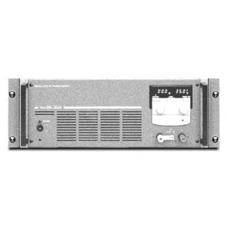
High-Reliability DC Power Supplies PAN-A Series
- Low noise and highly stable output achieved using the series regulation system
- Basic DC power supplies, superior for general-purpose use.
Features
DC power supply PAN-A series with reliability and safety cultivated by experience!
The PAN-A series is a high-performance, highly reliable DC power supply unit featuring regulated variable voltage. These units are suitable for use in a range of fields including research and development, quality control, and production.
The PAN-A series consists of a pre-regulator using FETs and a series regulator using power transistors, providing the high-quality output characteristic of the latter as well as the low power-source harmonic distortion of choke input type phase control.
To achieve the high reliability and safety important for power supply, components of sufficient derating and long-proven mounting techniques are used throughout. All models are carefully designed and furnished with over voltage protection (OVP) and various safety functions.

| 175 W Type | 350 W Type | 700 W Type | 1000 W Type | |
|---|---|---|---|---|
| 16V Series | PAN16-10A | PAN 16-18A | PAN 16-30A | PAN 16-50A |
| 35V Series | PAN 35-5A | PAN 35-10A | PAN 35-20A | PAN 35-30A |
| 60V Series | PAN 60-3A | PAN 60-6A | PAN 60-10A | PAN 60-20A |
| 70V Series | PAN 70-2.5A | PAN 70-5A | PAN 70-8A | PAN 70-15A |
| 110V Series | PAN 110-1.5A | PAN 110-3A | PAN 110-5A | PAN 110-10A |
| 160V Series | PAN 160-1A | PAN 160-2A | PAN 160-3.5A | PAN 160-7A |
| 250V Series | PAN 250-2.5A | PAN 250-4.5A |
Low temperature drift
Carefully selected components, improved circuit design, and heat dissipation based on the forced air cooling design have achieved a low- temperature drift of 100 ppm/°C (constant voltage characteristic) and 300 ppm/°C (constant current characteristic).
Quick transient response
Since the Error Amplifier has a characteristics of wide frequency bandwidth, stable gain, less phase shift and high loop gain, the PAN-A series is equipped with a highly stable and low output impedance as well as quick response to sudden change of the load.Typical response time is 50 μs
Applications
Incorporates a wide range of functions capable of systematization, including analog signal- or computer- (GPIB) based remote control, remote sensing, and master-slave-control serial and parallel operations.

Applications
The PAN-A series enables remote control of output voltage and current using analog signals. External contact points can also be used to control ON/OFF operations
Remote-control using external voltage
| Item to be controlled | Control voltage*1 | Input impedance |
|---|---|---|
| Output voltage | 0 to approx. 10V | Approx. 10 kΩ |
| Output current | 0 to approx. 10V | Approx. 25 kΩ |
*1 The control voltage circuit should be floated (insulated), since “common” is connected to the positive voltage side.
Remote-control using external resistor
| Item to be controlled | Control resistor*1 | Current in resistor |
|---|---|---|
| Output voltage | Approx. 10 kΩ | Approx. 1 mA |
| Output current | Approx. 10 kΩ | Approx. 0.4 mA |
*1 For the control resistors, use metal film or wire wound resistors of 1/2 W or larger capacity, a low temperature coefficient, and good aging stability.
Output On/Off Control
The output can be controlled to turn on or off using an external contact signal.
Master-slave parallel operation

(This control is possible only for series connected units of the same model.)
- The current capacity can be increased by connecting a multiple number of units of the same model in parallel. Output control can be performed by a master unit.
- Use only one master unit to perform remote sensing, remote control, and output on/off control.
*For one master unit, a maximum of two slave units can be connected in parallel.
Master-slave control of series operation

(This control is possible only for series connected units of the same model.)
- The output voltage can be increased by connecting a multiple number of units of the same model in series. The unit on the top (i.e., the positive side) plays the role of master, and can control the output of
the slave unit(s). - The example shown above is a dual tracking power supply that can vary positive and negative voltages simultaneously.
The number of slave units that can be connected in series depends on the rated output voltage and the isolation voltage of the power supply units.
Taking the PAN35-10A as an example for series connection: Since the rated output voltage is 35 V, and the
isolation voltage is ±250 V, 250/35 = 7.1, i.e., up to 7 units including the master unitcan be connected in series.
* PAN350-3.5A and PAN600-2A do not offer master-slave control and serial operation functions.
Remote sensing

- This is a method used to compensate for the voltage drop caused by the cable resistance between the power unit and the load and contact resistance. The problem of voltage drops becomes more serious as the current becomes larger. By turning on the “Sens” switch at the rear panel and transferring the voltage sensing point to the load , a voltage drop of up to 0.6V can be prevented on one side.
For the sensing function in 16 V models, the maximum output voltage of this series is 105% of the rated voltage, which is 16.8 V. Attempting to compensate for a voltage drop of 1.2 V (0.6 V one-way × 2), the full-compensating voltage, will prevent the output from reaching the rated voltage. In such cases, use wires with a larger cross-sectional area to reduce voltage drop to 0.4 V or less one-way. - Connect an electrolytic capacitor with a capacity of a several thousand to several tens of thousand of microfarads to the load end, paying attention to the polarity and making the lead wires as short as possible. The reasoning here is as follows. A long cable to the load has nonnegligible inductance, which raises the output impedance of the power supply unit to the load. A large capacitance connected to the load end can prevent this. Particularly when dealing with a load like an inverter, which t u r ns the current on and off with high frequency, connect a capacitor with a capacity larger than several thousand microfarad using the shortest possible lead wires.
Protection system
Overvoltage protector (OVP)
If an over voltage is generated by an operating error or accident, the OVP instantaneously (Operating time: 50 ms or less ) shuts down the power switch circuit protector, and protects the connected load. (Type 0 and Type I2 models employ a gate block system, and shut down their rectification circuits.) Since the OVP used in the PAN-A series is of a preset design, the operating voltage can be preset by pressing the preset knob on the panel, while looking at the voltmeter. The operating voltage can be checked without interrupting the OVP operation even during aging.
Overheat protection circuit
This circu it functions to turn off the power switch, if the temperature of some of the main components in the equipment rises higher than a specified value. A thermal fuse incorporated in the main- or sub-transformer further improves safety performance.
Voltage detection circuit
If the smoothing electrolytic capacitor voltage rises above a specified level owing to an operating error involving the remote selection switch inside the panel or to a failure of the rectification circuit, the voltage detection circuit functions to instantaneously shut down the rectification circuit.
Surge absorber
This protect the power supply unit from surge currents generated in the power line by lightning.
Reverse connection prevention circuit
This circuit protects the power supply unit even if a reverse polarity voltage is applied to the output terminals.
Overcurrent detection circuit
Using a comparison amplifier, this detection circuit constantly monitors the output current. It prevents a current from increasing beyond the rated value in the event of an over-input caused by remote control, and also prevents overcurrents caused by misoperation of the remote control selector located inside the panel.
Reference
About the load
Since the PAN-A series is designed for a wide range of applications, there are a variety of loads to be connected. Depending on the type of load, direct connection may cause problems or malfunctions, and some countermeasures should be taken.
Load with accumulated energy, such as a battery
When connecting a load with accumulated energy, such as a battery, to the PAN-A series output, a large current may flow from the load to the inter nal capacitor through the output control circuit protection diode. This current may burn internal components or shorten the load’s life. In such a cases, therefore, connect a reverse current protection diode between the power supply unit and the load as shown below.

When the load current has peaks or a pulse waveform
In the case of a digital or a motor driving circuit, a load current waveform will instantaneously reach the rated current range if the peak value exceeds the rated value, even if it is within the rated value on the meter indication (mean value). If so, the output voltage will drop and appear unstable. The basic remedy is to increase the output current (i.e., increase the current preset value or current capacity). However, if the pulse width is narrow or the peak value is low, it may prove effective to connect a large-capacitor to the load end.

Inductive load
The counter electromotive force generated by turning on and off of the power supply, or changing the voltage setting is shunted by protection diode D1 inserted in parallel with the out put so that the power supply is not damaged.
When pulse noise generated from an inductive load is impressed at the same polarity as the power supply, protect the power supply by inserting diode D2 in series with the power supply and inserting a noise prevention CR absorber across the switch.

When the output is turned On and off with a mechanical switch
When a DC output of 100V or more is opened and closed with a switch, arc discharge, etc. will cause the switch contacts to noticeably wear and generate noise. This noise may enter the power supply differential amplifier through the load line and cause the output to become unstable. Take noise counter measures by inserting a CR absorber near the contacts, the same as for an inductive load.
When performing remote sensing, always turn the sensing line on or off simultaneously.

Rush Current
When turning on the power, a rush current may flow, depending on when the power is turned on. Such rush currents are caused by magnetic saturation of the transformer core material. Theoretically, if the power is turned on near the phase angle 90°(π/2) of the voltage waveform, no rush current is generated. If the power is turned on at a timing corresponding to the phase angle 0°(zero cross), however, a max. current is generated. This transient phenomenon is shown below. In practice, however, the presence of a rush current is determined by the hysteresis character istic of the B-H curve of the core material, the direction of residual magnetic flux upon switch-off, and/or the impedance of the AC line to which the PAN-A series is connected. If the power is turned on simultaneously for a multiple number of the PAN-A series units, check that the AC line capacity or the switch board capacity is sufficient.
Typical (max.) rush current value for the PAN-A series
(Half wave width of current waveform: approx. 5 ms)
| Type | 0 | I2 | I3 | II |
|---|---|---|---|---|
| AC input power voltage | 100V | 100V | 100V | 100V |
| Peak current | 100A | 200A | 350A | 450A |

Negative voltage
With the OUTPUT switch set to OFF, a negative voltage of approx. 0.6V is applied to the output when the current setting knob is turned completely cou nterclock wise. This voltage acts to generate approx. 10mA of reverse cur rent through the load. The PAN-A series may be inadequate for applications in which the load should be kept free from serious influence by such a reverse current.
Output terminals on the front side
The output terminals on the front side are auxiliary output terminals. These terminals may not satisfy the specification. For models with a rated output voltage of 60 V or higher, be sure to use the attached terminal cover.
* PAN16-50A is not equipped with this feature.
Output wires
The sectional area, current capacity, and resistance of these wires are as shown below.
| Nominal sectional area | Current estimated for DC output wire | Current for allowable conductor temperature 60°C(Ambient temperature 30°C ) | Typical resistance at 20°C |
|---|---|---|---|
| 2〔mm2〕 | 10〔A〕 | 27〔A〕 | Approx.9(Ω/km) |
| 5.5 | 20 | 49 | 3 |
| 8 | 30 | 61 | 2.2 |
| 14 | 50 | 88 | 1.2 |
Specifications
Output: 16V
| Model | PAN16-10A | PAN16-18A | PAN16-30A | PAN16-50A*1 | |
|---|---|---|---|---|---|
| Output | CV(V) | 0 to 16 | |||
| CC(A) | 0 to 10 | 0 to 18 | 0 to 30 | 0 to 50 | |
| Ripple | CV(mVrms) | 0.5 | |||
| CC(mArms) | 2 | 5 | 10 | ||
| Line regulation | CV(mV) | 0.005%+2 | 0.005%+1 | ||
| CC(mA) | 1 | 3 | |||
| Load regulation | CV(mV) | 0.005%+2 | 0.005%+1 | 0.005%+2 | |
| CC(mA) | 3 | 5 | |||
| Dimensions | Type *2 | 0 | Ⅰ2 | Ⅰ3 | Ⅱ |
| Weight | kg(Approx.) | 11 | 17 | 23 | 36 |
| Input | Voltage [ AC ] (V) | 100 | |||
| Power consumption(Approx. kVA) | 0.4 | 0.8 | 1.1 | 1.6 | |
*1 PAN-16-50A does not have a front output terminal. *2 Dimensions (Type) 175W Type (Type 0): 106 (115) W x 140 (175) H x 400 (470) Dmm, 350W Type (Type I2): 210 (235) W x 140 (160) H x 350 (425) Dmm, 700W Type (Type I3): 210 (235) W x 140 (160) H x 400 (505) Dmm, 1kW type (TYPE II): 430W x 160 (175) H x 400 (505) Dmm
Output: 35V
| Model | PAN35-5A | PAN35-10A | PAN35-20A | PAN35-30A | |
|---|---|---|---|---|---|
| Output | CV(V) | 0 to 35 | |||
| CC(A) | 5 | 0 to 10 | 0 to 20 | 0 to 30 | |
| Ripple | CV(mVrms) | 0.5 | |||
| CC(mArms) | 1 | 2 | 3 | 5 | |
| Line regulation | CV(mV) | 0.005%+1 | |||
| CC(mA) | 1 | 3 | |||
| Load regulation | CV(mV) | 0.005%+1 | 0.005%+2 | 0.005%+1 | |
| CC(mA) | 2 | 3 | 5 | ||
| Dimensions | Type *1 | 0 | Ⅰ2 | Ⅰ3 | Ⅱ |
| Weight | kg(Approx.) | 11 | 17 | 23 | 36 |
| Input | Voltage [ AC ] (V) | 100 | |||
| Power consumption(Approx. kVA) | 0.4 | 0.8 | 1.4 | 1.8 | |
*1 Dimensions (Type) 175W Type (Type 0): 106 (115) W x 140 (175) H x 400 (470) Dmm, 350W Type (Type I2): 210 (235) W x 140 (160) H x 350 (425) Dmm, 700W Type (Type I3): 210 (235) W x 140 (160) H x 400 (505) Dmm, 1kW type (TYPE II): 430W x 160 (175) H x 400 (505) Dmm
Output: 60V
| Model | PAN60-3A | PAN60-6A | PAN60-10A | PAN60-20A | |
|---|---|---|---|---|---|
| Output | CV(V) | 0 to 60 | |||
| CC(A) | 0 to 3 | 0 to 6 | 0 to 10 | 0 to 20 | |
| Ripple | CV(mVrms) | 0.5 | |||
| CC(mArms) | 1 | 2 | 3 | 2 | |
| Line regulation | CV(mV) | 0.005%+1 | |||
| CC(mA) | 1 | 3 | 1 | ||
| Load regulation | CV(mV) | 0.005%+1 | |||
| CC(mA) | 2 | 3 | 2 | ||
| Dimensions | Type *1 | 0 | Ⅰ2 | Ⅰ3 | Ⅱ |
| Weight | kg(Approx.) | 11 | 17 | 22 | 36 |
| Input | Voltage [ AC ] (V) | 100 | |||
| Power consumption(Approx. kVA) | 0.35 | 0.7 | 1.1 | 2.1 | |
*1 Dimensions (Type) 175W Type (Type 0): 106 (115) W x 140 (175) H x 400 (470) Dmm, 350W Type (Type I2): 210 (235) W x 140 (160) H x 350 (425) Dmm, 700W Type (Type I3): 210 (235) W x 140 (160) H x 400 (505) Dmm, 1kW type (TYPE II): 430W x 160 (175) H x 400 (505) Dmm
Output: 70V
| Model | PAN70-2.5A | PAN70-5A | PAN70-8A | PAN70-15A | |
|---|---|---|---|---|---|
| Output | CV(V) | 0 to 70 | |||
| CC(A) | 0 to 2.5 | 5 | 0 to 8 | 0 to 15 | |
| Ripple | CV(mVrms) | 0.5 | 1 | ||
| CC(mArms) | 1 | 2 | 5 | ||
| Line regulation | CV(mV) | 0.005%+1 | |||
| CC(mA) | 1 | ||||
| Load regulation | CV(mV) | 0.005%+1 | |||
| CC(mA) | 1 | 2 | 3 | ||
| Dimensions | Type *1 | 0 | Ⅰ2 | Ⅰ3 | Ⅱ |
| Weight | kg(Approx.) | 11 | 17 | 22 | 35 |
| Input | Voltage [ AC ] (V) | 100 | |||
| Power consumption(Approx. kVA) | 0.35 | 0.8 | 1.1 | 1.9 | |
*1 Dimensions (Type) 175W Type (Type 0): 106 (115) W x 140 (175) H x 400 (470) Dmm, 350W Type (Type I2): 210 (235) W x 140 (160) H x 350 (425) Dmm, 700W Type (Type I3): 210 (235) W x 140 (160) H x 400 (505) Dmm, 1kW type (TYPE II): 430W x 160 (175) H x 400 (505) Dmm
Output: 110V
| Model | PAN110-1.5A | PAN110-3A | PAN110-5A | PAN110-10A | |
|---|---|---|---|---|---|
| Output | CV(V) | 0 to 110 | |||
| CC(A) | 0 to 1.5 | 0 to 3 | 5 | 0 to 10 | |
| Ripple | CV(mVrms) | 0.5 | 1 | ||
| CC(mArms) | 1 | 2 | |||
| Line regulation | CV(mV) | 0.005%+1 | |||
| CC(mA) | 1 | ||||
| Load regulation | CV(mV) | 0.005%+1 | |||
| CC(mA) | 1 | 2 | 3 | ||
| Dimensions | Type *1 | 0 | Ⅰ2 | Ⅰ3 | Ⅱ |
| Weight | kg(Approx.) | 11 | 17 | 22 | 35 |
| Input | Voltage [ AC ] (V) | 100 | |||
| Power consumption(Approx. kVA) | 0.4 | 0.7 | 1.0 | 2.0 | |
*1 Dimensions (Type) 175W Type (Type 0): 106 (115) W x 140 (175) H x 400 (470) Dmm, 350W Type (Type I2): 210 (235) W x 140 (160) H x 350 (425) Dmm, 700W Type (Type I3): 210 (235) W x 140 (160) H x 400 (505) Dmm, 1kW type (TYPE II): 430W x 160 (175) H x 400 (505) Dmm
Output: 160V
| Model | PAN160-1A | PAN160-2A | PAN160-3.5A | PAN160-7A | |
|---|---|---|---|---|---|
| Output | CV(V) | 0 to 160 | |||
| CC(A) | 0 to 1 | 0 to 2 | 0 to 3.5 | 0 to 7 | |
| Ripple | CV(mVrms) | 1 | |||
| CC(mArms) | 1 | 2 | |||
| Line regulation | CV(mV) | 0.005%+1 | |||
| CC(mA) | 1 | ||||
| Load regulation | CV(mV) | 0.005%+1 | 0.005%+2 | ||
| CC(mA) | 1 | 2 | |||
| Dimensions | Type *1 | 0 | Ⅰ2 | Ⅰ3 | Ⅱ |
| Weight | kg(Approx.) | 11 | 17 | 22 | 36 |
| Input | Voltage [ AC ] (V) | 100 | |||
| Power consumption(Approx. kVA) | 0.33 | 0.7 | 1 | 1.9 | |
*1 Dimensions (Type) 175W Type (Type 0): 106 (115) W x 140 (175) H x 400 (470) Dmm, 350W Type (Type I2): 210 (235) W x 140 (160) H x 350 (425) Dmm, 700W Type (Type I3): 210 (235) W x 140 (160) H x 400 (505) Dmm, 1kW type (TYPE II): 430W x 160 (175) H x 400 (505) Dmm
Output: 250V, 350V, 600V
| Model | PAN250-2.5A | PAN250-4.5A | PAN350-3.5A | PAN600-2A | |
|---|---|---|---|---|---|
| Output | CV(V) | 0 to 250 | 0 to 350 | 0 to 600 | |
| CC(A) | 0 to 2.5 | 0 to 4.5 | 0 to 3.5 | 0 to 2 | |
| Ripple | CV(mVrms) | 5 | 1 | ||
| CC(mArms) | 2 | 0.5 | |||
| Line regulation | CV(mV) | 0.005%+2 | 0.005%+1 | ||
| CC(mA) | 1 | 0.5 | |||
| Load regulation | CV(mV) | 0.005%+3 | 0.005%+1 | 0.002%+1 | |
| CC(mA) | 1 | 2 | 1 | ||
| Dimensions | Type *1 | Ⅰ3 | Ⅱ | ||
| Weight | kg(Approx.) | 23 | 35 | 36 | 37 |
| Input | Voltage [ AC ] (V) | 100 | |||
| Power consumption(Approx. kVA) | 1.1 | 1.8 | 2.1 | 2.0 | |
*1 Dimensions (Type) 175W Type (Type 0): 106 (115) W x 140 (175) H x 400 (470) Dmm, 350W Type (Type I2): 210 (235) W x 140 (160) H x 350 (425) Dmm, 700W Type (Type I3): 210 (235) W x 140 (160) H x 400 (505) Dmm, 1kW type (TYPE II): 430W x 160 (175) H x 400 (505) Dmm
Common specifications
| Constant voltage temperature coefficient | 100 p.p.m./°C (standard value) |
|---|---|
| Constant current temperature coefficient | 300 p.p.m./°C (standard value) |
| Transient response time | 50 μs: Time required for the output voltage to return to a value less than 0.05 % of the rated value + 10 mV, against a fluctuation of 5 % to 100 % of the output current. |
| Ripple noise | Using an AC voltmeter having a range of 5 Hz to 1 MHz, ±3 dB, indicated in mean value and effective value measurement is performed with either a positive or negative output terminal connected to the ground. |
| Indication meters | Voltmeter indication error : ±(0.5 % rdg + 2 digits) at 23 °C ±5 °C |
| Voltmeter max. indication digits : 199.9 (Note: 19.99 for the PAN16-10A/PAN16- 18A/PAN16-30A/PAN16-50A models, and 1999 for the PAN250-2.5A/PAN250-4.5A/ PAN600-2A) | |
| Amperemeter indication error : ±(1 % rdg + 5 digits) at 23 °C ±5 °C | |
| Amperemeter max. indication digits : 19.99 (Note: 1.999 for the PAN110-1.5A/ PAN160-1A, and 199.9 for the PAN16-30A/ PAN16-50A/PAN35-20A/PAN35-30A/PAN60- 20A) | |
| Grounding | Plus or minus terminal can be grounded |
| Isolation voltage | ±250V DC (However, ±500 VDC for the PAN110-1.5A/PAN110-3A/PAN110-5A/ PAN110-10A/PAN160-1A/PAN160-2A/ PAN160-3.5A/PAN250-2.5A/PAN250-4.5A.) (However, PAN350-3.5A and PAN600-2A are ±1000V DC) |
| Insulation resistance | Across input side and chassis: Greater than 30 MΩ at 500 VDC |
| Across output side and chassis: Greater than 20 MΩ at 500 VDC (For PAN350-3.5A and PAN600-2A, this is 1000 V DC, 20 MΩ, or higher.) | |
| Withstand voltage | Nothing abnormal should occur at 1500 VAC, 1 min. |
| Operating temperature range | 0° to 40°C |
| Operating humidity range | 10 to 90 % RH |
| Cooling method | Forced air cooling using fan |
| Constant voltage operation | Green LED |
| Constant current operation | Red LED |
| Protection devices | Constant voltage, constant current automatic crossover |
| Overvoltage protector (OVP) (10 % to 110 % of rated output voltage) | |
| Overcurrent protection circuit (Approx. 110 % of rated output current) | |
| Overvoltage protection circuit (Smoothing electrolytic capacitor for the rectification circuit) | |
| Overheat protection circuit (OHP) (Semiconductor cooling heat-sink [100 °C]) | |
| Thermal fuse (Main- or sub-transformer) | |
| Input/output fuse | |
| Input surge absorber | |
| About input voltage | If you require a power supply voltage other than 100V, please contact us at the time of order placement. (Factory option) |
| Dimensions (maximum dimension) | Type 0: 106(4.17˝)W ✕ 140(5.51˝)H ✕ 400(15.75˝)Dmm(inch) Type I 2: 210(8.27˝)W ✕ 140(5.51˝)H ✕ 350(13.78˝)Dmm(inch) Type I 3: 210(8.27˝)W ✕ 140(5.51˝)H ✕ 400(15.75˝)Dmm(inch) Type II: 430(16.93˝)W ✕ 160(6.3˝)H ✕ 400(15.75˝)Dmm(inch) |
Line-up

Options
Series options. For more information on optional products, please refer to the individual product pages.