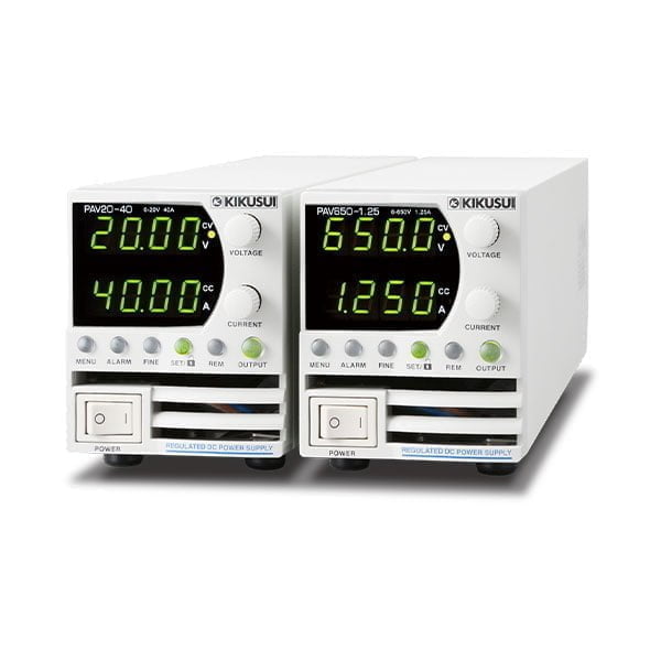


Compact Variable-switching Regulated DC Power Supply
PAV Series – 200W model
価格お問い合わせ
- 2U bench-top type
- Palm-sized, portable power supply
- Output power: 200W/400W/600W/800W 4models
- Output voltage: 10V to 650V 8models
- USB/RS232C/RS485 as standard interface (*LAN is a factory option)
- 64 models total (LAN model included)
| Image | SKU | Output CV [V] | Output CC [A] | 標準価格 | WEBかんたんお見積り | ||
|---|---|---|---|---|---|---|---|
 | PAV10-20 | 10V | 20 | 5 | 25 | オープン価格(お問い合わせください) | |
| PAV10-20 with LAN | 10V | 20 | 5 | 25 | オープン価格(お問い合わせください) | |
| PAV20-10 | 20V | 10 | 6 | 15 | オープン価格(お問い合わせください) | |
| PAV20-10 with LAN | 20V | 10 | 6 | 15 | オープン価格(お問い合わせください) | |
| PAV36-6 | 36V | 6 | 6 | 8 | オープン価格(お問い合わせください) | |
| PAV36-6 with LAN | 36V | 6 | 6 | 8 | オープン価格(お問い合わせください) | |
| PAV60-3.5 | 60V | 3.5 | 7 | 4 | オープン価格(お問い合わせください) | |
| PAV60-3.5 with LAN | 60V | 3.5 | 7 | 4 | オープン価格(お問い合わせください) | |
| PAV100-2 | 100V | 2 | 8 | 3 | オープン価格(お問い合わせください) | |
| PAV100-2 with LAN | 100V | 2 | 8 | 3 | オープン価格(お問い合わせください) | |
| PAV160-1.3 | 160V | 1.3 | 10 | 1.2 | オープン価格(お問い合わせください) | |
| PAV160-1.3 with LAN | 160V | 1.3 | 10 | 1.2 | オープン価格(お問い合わせください) | |
| PAV320-0.65 | 320V | 0.65 | 25 | 0.8 | オープン価格(お問い合わせください) | |
| PAV320-0.65 with LAN | 320V | 0.65 | 25 | 0.8 | オープン価格(お問い合わせください) | |
| PAV650-0.32 | 650V | 0.32 | 60 | 0.5 | オープン価格(お問い合わせください) | |
| PAV650-0.32 with LAN | 650V | 0.32 | 60 | 0.5 | オープン価格(お問い合わせください) |
Line-up
| Image | SKU | Output CV [V] | Output CC [A] | 標準価格 | WEBかんたんお見積り | ||
|---|---|---|---|---|---|---|---|
| PAV10-20 | 10V | 20 | 5 | 25 | オープン価格(お問い合わせください) | |
| PAV10-20 with LAN | 10V | 20 | 5 | 25 | オープン価格(お問い合わせください) | |
| PAV20-10 | 20V | 10 | 6 | 15 | オープン価格(お問い合わせください) | |
| PAV20-10 with LAN | 20V | 10 | 6 | 15 | オープン価格(お問い合わせください) | |
| PAV36-6 | 36V | 6 | 6 | 8 | オープン価格(お問い合わせください) | |
| PAV36-6 with LAN | 36V | 6 | 6 | 8 | オープン価格(お問い合わせください) | |
| PAV60-3.5 | 60V | 3.5 | 7 | 4 | オープン価格(お問い合わせください) | |
| PAV60-3.5 with LAN | 60V | 3.5 | 7 | 4 | オープン価格(お問い合わせください) | |
| PAV100-2 | 100V | 2 | 8 | 3 | オープン価格(お問い合わせください) | |
| PAV100-2 with LAN | 100V | 2 | 8 | 3 | オープン価格(お問い合わせください) | |
| PAV160-1.3 | 160V | 1.3 | 10 | 1.2 | オープン価格(お問い合わせください) | |
| PAV160-1.3 with LAN | 160V | 1.3 | 10 | 1.2 | オープン価格(お問い合わせください) | |
| PAV320-0.65 | 320V | 0.65 | 25 | 0.8 | オープン価格(お問い合わせください) | |
| PAV320-0.65 with LAN | 320V | 0.65 | 25 | 0.8 | オープン価格(お問い合わせください) | |
| PAV650-0.32 | 650V | 0.32 | 60 | 0.5 | オープン価格(お問い合わせください) | |
| PAV650-0.32 with LAN | 650V | 0.32 | 60 | 0.5 | オープン価格(お問い合わせください) |
Specifications
PAV Series 200W model
Output
| Item/Model | PAV10-20 | PAV20-10 | PAV36-6 | PAV60-3.5 | PAV100-2 | PAV160-1.3 | PAV320-0.65 | PAV650-0.32 |
|---|---|---|---|---|---|---|---|---|
| Rated output voltage *1 | 10V | 20V | 36V | 60V | 100V | 160V | 320V | 650V |
| Rated output current *2 | 20A | 10A | 6A | 3.5A | 2A | 1.3A | 0.65A | 0.32A |
| Rated output power | 200W | 200W | 216W | 210W | 200W | 208W | 208W | 208W |
AC input
| Item/Model | PAV10-20 | PAV20-10 | PAV36-6 | PAV60-3.5 | PAV100-2 | PAV160-1.3 | PAV320-0.65 | PAV650-0.32 |
|---|---|---|---|---|---|---|---|---|
| Nominal input rating | 100 Vac to 240 Vac continuous input, 50 Hz to 60 Hz, single phase | |||||||
| Input voltage range | 85 Vac to 265 Vac | |||||||
| Input frequency range | 47 Hz to 63 Hz | |||||||
| Input current (typ) *3 (100 Vac/200 Vac) | 2.65A/1.31A | 2.62A/1.29A | 2.76A/1.37A | 2.69A/1.33A | 2.55A/1.26A | 2.64A/1.30A | ||
| Power factor (typ) (100 Vac/200 Vac, at the rated output power) | 0.99/0.98 | |||||||
| Efficiency (typ) *3 | 76%/77.5% | 77%/79% | 79%/80.5% | 79%/80.5% | 79%/81% | 79%/81% | ||
| Inrush current (100 Vac/200 Vac) *4 | 15 A / 30 A or less | 25 A / 25 A or less | ||||||
Constant voltage mode
| Item/Model | PAV10-20 | PAV20-10 | PAV36-6 | PAV60-3.5 | PAV100-2 | PAV160-1.3 | PAV320-0.65 | PAV650-0.32 | |
|---|---|---|---|---|---|---|---|---|---|
| Maximum line regulation *5 (for the rated output voltage) | 0.01% +2mV | 0.01% | |||||||
| Maximum load regulation *6 (for the rated output voltage) | |||||||||
| Ripple noise *7 | 20 MHz, p-p | 50mV | 50mV | 50mV | 50mV | 80mV | 100mV | 150mV | 250mV |
| 5 Hz to 1 MHz, rms | 5mV | 6mV | 6mV | 7mV | 8mV | 10mV | 25mV | 60mV | |
| Temperature coefficient | 30 PPM /°C (after a 30 minute warm-up, for the rated output voltage) | ||||||||
| Aging drift *8 (for the rated output voltage) | 0.02% | ||||||||
| Initial drift *9 (for the rated output voltage) | 0.05% +2mV | 0.05% | |||||||
| Maximum remote sensing compensation voltage (single line (positive or negative)) | 1V | 1V | 2V | 3V | 5V | 5V | |||
| Rise time *10 | 15ms | 30ms | 30ms | 50ms | 50ms | 110ms | 170ms | 170ms | |
| Fall time | At full load *10 | 12ms | 25ms | 30ms | 40ms | 50ms | 180ms | 270ms | 270ms |
| Td (typ) *11 | 210ms | 250ms | 320ms | 380ms | 1200ms | — | |||
| No load a *12 | 40ms | 65ms | 85ms | 100ms | 250ms | — | |||
| No load b *13 | 200ms | 200ms | 290ms | 310ms | 1100ms | 2000ms | 2500ms | 3000ms | |
| Transient response time *14 | 1 ms or less | 2 ms or less | |||||||
| Output hold time (typ) *15 | 15ms | 16ms | 16ms | 16ms | 15ms | ||||
Constant current mode
| Item/Model | PAV10-20 | PAV20-10 | PAV36-6 | PAV60-3.5 | PAV100-2 | PAV160-1.3 | PAV320-0.65 | PAV650-0.32 |
|---|---|---|---|---|---|---|---|---|
| Maximum line regulation *5 (at the rated output current) | 0.01% +2mA | 0.02% | ||||||
| Maximum load regulation *16 (at the rated output current) | 0.01% +5mA | 0.09% | 0.15% | |||||
| Change in the load due to the temperature drift of internal components (at the rated output current) | 0.05% or less (for 30 minutes after the load conditions are changed) | |||||||
| Ripple noise *17 (5 Hz to 1 MHz, rms) | 25mA | 15mA | 8mA | 4mA | 3mA | 1.2mA | 0.8mA | 0.5mA |
| Temperature coefficient | 100PPM/℃(30分ウォームアップ後、定格出力電流に対して) | |||||||
| Aging drift *8 (at the rated output current) | 0.05% | |||||||
| Initial drift *9 (at the rated output current) | 0.1% | |||||||
Protection functions
| Item/Model | PAV10-20 | PAV20-10 | PAV36-6 | PAV60-3.5 | PAV100-2 | PAV160-1.3 | PAV320-0.65 | PAV650-0.32 |
|---|---|---|---|---|---|---|---|---|
| Foldback protection | Turns off the output when the operation switches from constant voltage mode to constant current mode or vice versa. Can be set as necessary. | |||||||
| Overvoltage protection (OVP) | Inverter shutoff system. Prevents the output voltage from being set higher than the OVP value. Also shuts off the output when an output overvoltage (exceeding the OVP value) occurs. | |||||||
| Overvoltage protection voltage setting range | 0.5 V to 12 V | 1 V to 24 V | 2 V to 40 V | 5 V to 66 V | 5 V to 110 V | 5 V to 176 V | 5 V to 353 V | 5 V to 717 V |
| Undervoltage limit (UVL) | Prevents the output voltage from being set lower than the UVL value. Disabled during external control. | |||||||
| Undervoltage protection (UVP) | Shuts off the output when the output voltage falls below the UVP value. | |||||||
| Overheat protection | Shuts off the output before the temperature of the internal components exceeds the safe operation temperature. | |||||||
Setting and readback (USB, RS232, RS485, optional LAN interface)
| Item/Model | PAV10-20 | PAV20-10 | PAV36-6 | PAV60-3.5 | PAV100-2 | PAV160-1.3 | PAV320-0.65 | PAV650-0.32 | |
|---|---|---|---|---|---|---|---|---|---|
| Output Voltage Setting | Accuracy | 0.05% of the rated output voltage | 0.05% of the output voltage + 0.05% of the rated output voltage | ||||||
| Number of decimal digits | 3 digits | 2 digits | |||||||
| Resolution | Approx. 1/60000 of rated output voltage | ||||||||
| Output current setting | Accuracy *18 | 0.1% of output current + 0.1% of the rated output current | 0.2% of the rated output current | ||||||
| Number of decimal digits | 3 digits | 4 digits | |||||||
| Resolution | Approx. 1/60000 of rated output current | ||||||||
| Output voltage readback | Accuracy | 0.05% of the rated output voltage | 0.05% of the output voltage + 0.05% of the rated output voltage | ||||||
| Resolution | Approx. 1/60000 of rated output voltage | ||||||||
| Output current readback | Accuracy *18 | 0.1% of output current + 0.3% of the rated output current | |||||||
| Resolution | Approx. 1/60000 of rated output current | ||||||||
Front panel
| Item/Model | PAV10-20 | PAV20-10 | PAV36-6 | PAV60-3.5 | PAV100-2 | PAV160-1.3 | PAV320-0.65 | PAV650-0.32 | |
|---|---|---|---|---|---|---|---|---|---|
| Control function |
| ||||||||
| Output voltage display | Accuracy | 0.5% of the rated output voltage ± 1 count | |||||||
| Number of decimal digits | 2 digits | 1 digit | |||||||
| Output current display | Accuracy | 0.5% of the rated output current ± 1 count | |||||||
| Number of decimal digits | 2 digits | 3 digits | |||||||
| LED display | Green: FINE, MENU, SET, ALARM, REM, OUTPUT, CV, CC Red: ALARM (OVP, UVP, OTP, FOLD, AC FAIL) | ||||||||
| Setting keys | FINE, MENU, SET, ALARM, REM, OUTPUT | ||||||||
*1. The minimum voltage is 0.1 % of the rated output voltage. *2. The minimum current is 0.2 % of the rated output current. *3. Input voltage 100 Vac/200 Vac, at the rated output power, ambient temperature 25 °C If the LAN option is built in, the efficiency decreases by 0.5 % and the input current increases by 0.5 %. *4. Excludes input surge current (duration 0.2 ms or less) applied to the built-in noise filter section. *5. 85 Vac to 132 Vac or 170 Vac to 265 Vac, fixed load *6. With the input voltage held constant, the sensing point was measured using remote sensing from no load to full load. *7. Models with rated output voltages from 10 V to 100 V were measured using an RC- 9131 A 1:1 probe that conforms to the JEITA specifications. Models with rated output voltage from 160 V to 650 V were measured using a 10:1 probe. *8. When at least 8 hours has passed after a 30 minute warm-up with the input voltage, load, and ambient temperature held constant *9. For 30 minutes after turning on the power with the input voltage, load, and ambient temperature held constant *10. Between 10 % and 90 % of the rated resistive load and rated output voltage *11. If the output voltage is repeatedly decreased, Td is the minimum duration from a given voltage drop to the next voltage drop. *12. Duration for the voltage to change from 90 % to 10 % of the rated output voltage when the output voltage is repeatedly decreased and the duration from a given voltage drop to the next voltage drop is longer than Td. *13. Duration for the voltage to change from 90 % to 10 % of the rated output voltage when the output voltage is repeatedly decreased and the duration from a given voltage drop to the next voltage drop is shorter than Td. *14. The amount of time required for the output voltage to return to a value within 0.5 % of the rated output voltage. The change in the load current is 10 % to 90 % of the rating. The output voltage is between 10 % and 100 % of the rating. During local sensing. *15. At the rated output power *16. The value when the output voltage is changed from the lower limit to the rated voltage in constant current mode with the input voltage held constant *17. For models with a 10 V rated output voltage, this is the value for when the output voltage is 2 V to 10 V at the rated output current. For other models, this is the value for when the output voltage is 10 % to 100 % of the rating at the rated output current. Models with rated output voltage from 160 V to 650 V were measured using a 10:1 probe. *18. In output current control, the current, linearity, and monitor accuracies do not include the load variation caused by initial drift and temperature drift of internal components.
*12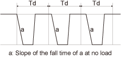 *13
*13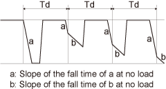
Specifications common to all types
External control
| Output voltage control using external voltage | 0% to 100% of the rated output voltage (application voltage range selectable: 0 V to 5 V or 0 V to 10 V) Accuracy and linearity: ± 0.5% of the rated output voltage |
|---|---|
| Output current control using external voltage *1 | 0% to 100% of the rated output current (application voltage range selectable: 0 V to 5 V or 0 V to 10 V) Accuracy and linearity: ± 1% of the rated output current |
| Output voltage control using external resistance | 0% to 100% of the rated output voltage (application resistance range selectable: 0 Ω to 5 kΩ or 0 Ω to 10 kΩ) Accuracy and linearity: ± 1% of the rated output voltage |
| Output current control using external resistance *1 | 0% to 100% of the rated output current (application resistance range selectable: 0 Ω to 5 kΩ or 0 Ω to 10 kΩ) Accuracy and linearity: ± 1.5% of the rated output current |
| Output shutoff (SO) control | External voltage application: 0 V to 0.6 V, 4 V to 15 V, or a contact switch. Positive or negative logic selectable. |
| Output current monitor *1 | Monitor voltage range selectable: 0 V to 5 V or 0 V to 10 V, Accuracy: 1% |
| Output voltage monitor | Monitor voltage range selectable: 0 V to 5 V or 0 V to 10 V, Accuracy: 1% |
| Normal operation status signal | Normal (4 V to 5 V), abnormal (0 V), output resistance 500 Ω |
| Parallel operation *2 *3 | Possible up to six power supplies. Master-slave operation with a current balance function. |
| Series operation *4 | Possible up to two power supplies. |
| Constant voltage/constant current mode (CV/CC) signal | Open collector output (maximum application voltage 30 V, maximum sink current 10 mA) Low level (on) during constant current (CC) mode High level (off) during constant voltage (CV) mode |
| Output on / off control (ILC) | Output can be shut off using a contact switch or the like (maximum voltage between terminals: 5 V). When open: Output off When shorted: Output on |
| Local / remote | Can be switched by applying an external voltage or by opening or shorting the circuit. Local: 2 V to 15 V or open Remote: 0 V to 0.6 V or shorted |
| External control status signal | Open collector output (maximum application voltage 30 V, maximum sink current 10 mA) High level (off) during local mode Low level (on) during external control |
| Trigger output signal | Maximum low level output signal: 0.8 V Minimum high level output signal: 3.8 V, maximum high level output signal: 5 V Maximum source current: 16 mA, output trigger signal span: 20 μs (typ) |
| Trigger input signal | Maximum low level input signal: 1.2V Minimum high level input signal: 3.5 V, maximum high level input signal: 5 V Maximum sink current: 16 mA, positive edge trigger span: 10 μs (min) Tr/Tf: 1 μs (max) |
| Program signal output 1 | Open collector output (maximum application voltage 25 V, maximum sink current 100 mA) |
| Program signal output 2 |
*1. In output current control, the current, linearity, and monitor accuracies do not include the load variation caused by initial drift and temperature drift of internal components. *2. For parallel operation of two or more PAV series power supplies with the same rating, the minimum load current is 5% of the rating or higher. For parallel operation of four or less models with rated output voltage of 160 V to 650 V, the minimum load current is 5% of the rating or higher. For parallel operation of more than four, the minimum load current is 20% of the rating or higher. *3. The ammeter’s display accuracy when the total current is displayed on the master unit is 2% ± 1 count of the total of rated currents. *4. An external protection diode is necessary.
Environmental conditions
| Operating ambient temperature and humidity | 0 °C to 50 °C (32 °F to 122 °F) 20%rh to 90%rh (no condensation) |
|---|---|
| Storage ambient temperature and humidity | -20 °C to 85 °C (-4 °F to 185 °F) 10%rh to 95%rh (no condensation) |
| Installation location | Indoors, overvoltage category II Altitude: Up to 3000 m (at 2000 m and above, the operating ambient temperature must be reduced), At 2000 m to 3000 m, the operating ambient temperature is 0 °C to 40 °C (32 °F to 104 °F). |
Structure
| Cooling system | Forced air cooling using internal fan |
|---|---|
| Weight | 1.9 kg (4.2 lb) or less: 200 W, 400 W types (models whose rated output voltage is 10 V to 100 V and 160 V to 650 V) 2.0 kg (4.4 lb) or less: 600 W, 800 W types (models whose rated output voltage is 160 V to 650 V) 2.1 kg (4.6 lb) or less: 600 W, 800 W types (models whose rated output voltage is 10 V to 100 V) |
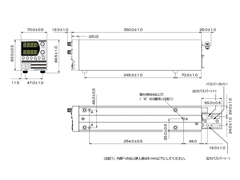
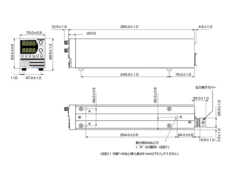
| Dimensions | See outline drawing. |
| Vibration resistance | IEC60068-2-64 |
| Shock resistance | 196.1 m/s2 (20 G) or less, half sine, 11 ms, when not packaged, when not operating (IEC 60068-2-27) |
Safety / EMC
| Safety | Conforms to the requirements of the directive and standard below. Low Voltage Directive 2014/35/EU *2 UL/EN/IEC 61010-1 (Class I *1, Pollution degree 2 *2) (Design to meet UL/EN 60950-1) ● Models whose rated output voltage is 10 V, 20 V, 36 V, or 60 V Output terminals and signal terminals produce non-hazardous voltage. ● Models whose rated output voltage is 100 V, 160 V, 320 V, or 650 V Output terminals and J1 and J2 terminals produce hazardous voltage (other signal terminals produce non-hazardous voltage). | |
|---|---|---|
| EMC | Conforms to the requirements of the directive and standard below. EMC Directive 2014/30/EU EN/IEC 61326-1 (Design to meet EN 55022/EN 55024) | |
| Withstanding voltage *3 | ● Models whose rated output voltage is 10 V, 20 V, or 36 V 4242 Vdc: Between input and output (including between signal terminals) 2828 Vdc: Between input and FG 707 Vdc: Between output (including between signal terminals) and FG | ● Models whose rated output voltage is 60 V or 100 V 4242 Vdc: Between input and output (including between signal terminals) 2828 Vdc: Between input and FG 707 Vdc: Between signal terminals (excluding J1/J2) and FG 1910 Vdc: Between output as well as J1/J2 terminals and signal terminals (excluding J1/J2) 1380 Vdc: Between output as well as J1/J2 terminals and FG |
| ● Models whose rated output voltage is 160 V or 320 V 2970 Vdc: Between input and output (including between signal terminals) 2828 Vdc: Between input and FG 707 Vdc: Between signal terminals (excluding J1/J2) and FG 4242 Vdc: Between input and signal terminals (excluding J1/J2) 3200 Vdc: Between output as well as J1/J2 terminals and signal terminals (excluding J1/J2) 2000 Vdc: Between output as well as J1/J2 terminals and FG | ● Models whose rated output voltage is 650 V 3704 Vdc: Between input and output (including between signal terminals) 2828 Vdc: Between input and FG 707 Vdc: Between signal terminals (excluding J1/J2) and FG 4242 Vdc: Between input and signal terminals (excluding J1/J2) 4244 Vdc: Between output as well as J1/J2 terminals and signal terminals (excluding J1/J2) 2780 Vdc: Between output as well as J1/J2 terminals and FG | |
| Insulation resistance | 100 MΩ or higher (25 °C, 70%rh) | |
| Conducted emission | IEC/EN 61326-1, Class B, FCC part15-B, VCCI-B | |
| Radiated emission | IEC/EN 61326-1, Class A *4, FCC part15-A, VCCI-A | |
*1. This is a Class I equipment. Be sure to ground the product’s protective conductor terminal. The safety of this product is only guaranteed when the product is properly grounded. *2. Pollution is addition of foreign matter (solid, liquid or gaseous) that may produce a reduction of dielectric strength or surface resistivity. Pollution Degree 2 assumes that only non-conductive pollution will occur except for an occasional temporary conductivity caused by condensation. *3. Test voltage application time: 1 minute *4. This is a Class A equipment. The product is intended for use in an industrial environment. This product may cause interference if used in residential areas. Such use must be avoided unless the user takes special measures to reduce electromagnetic emissions to prevent interference to the reception of radio and television broadcasts.
Dimensions(mm)
Options
Power cord
* The main body includes a PAV-J.