
Transient Immunity TesterKES7700
Complying with International Standards!
Best Suited to EMC Testing for Automotive Components

Transient Immunity Tester
Transient Immunity Tester KES7700 Series are transient surge tester that utilizes a compact unit system. A surge generator circuit is installed for each pulse unit as the tester meets the requirement of ISO7637-2, ISO7637-3, ISO16750-2, JASO D001, SAEJ1113, and other standards. The KES7700 Series meets a broad range of independent automobile manufacturer standards as well.
The ISO7637 standard specifies Pulse 1, Pulse 2a, and Pulse 3a/3b, while the ISO16750-2 standard specifies Pulse 5a/5b. Each pulse simulates the following: electromagnetic phenomena produced by electronic equipment joined by wire harnesses during an automobile’s normal operation, electromagnetic coupling during switch opening and closing, and load dump surges produced by the alternator when the battery is disconnected. Each pulse also tests the tolerance of on-board electronic equipment. In this testing, malfunctions and breakdowns involving on-board electronic equipment are evaluated.
Applications
System Configuration
The KES7702/KES7703 main frame can be connected with up to 7 pulse modules (5 plug-in type modules + 2 external-connect type modules). By replacing pulse modules, it is possible to comply with various automotive manufacturer’s requirements, such as the ISO 7637-2 and JASO D001 standards.

*In the KES7700 series, each pulse module supports a specific surge waveform. If the related international standard is revised, the system can be upgraded simply by replacing pulse modules. This system architecture also makes it easy to meet individual auto makers’ test requirements.
Test reproducibility improvement
The KES7702/KES7703 mainframe are designed to simplify the setup of the test environment prescribed in the ISO7637-2 standards. Preparation of the test environment can lead to test reproducibility.

Output waveform stability
Placing the output system on the front surface and the power supply system and signal system on the rear surface made it possible to achieve stable transient surge output and communication control. Also, a bus bar was utilized for the output end. Since the input and communication control systems of each unit are separated from the output lines, malfunction of the tester itself due to transient surges being output is less likely to occur.
Test reproducibility
Since the lower part of mainframe KES7702/KES7703 testers is an SG unit, braided wire and other ground cables are unnecessary as a connection with a ground plane can be made.Also, the output terminal is set at a height of 50 mm from the ground plane (reference ground surface) as prescribed in the ISO7637-2 standards.
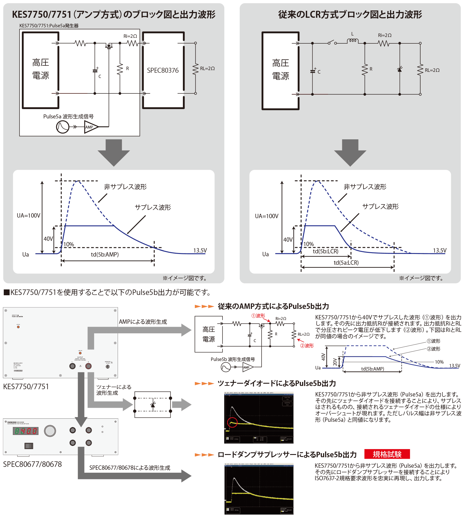
Pulse5b Meets ISO7637-2:2004 and ISO16750-2:2010 Standards
In the ISO7637-2 standard, it is specified that the Us (voltage value) setting for Pulse5b uses a ZD (Optional diode bridge), and the td (pulse width) “must be the same as Pulse5a.” Pulse generators are available in “LCR method” and “amplifier method,” and conventional Pulse5b generators typically use a combination of an LCR-method Pulse5a generator and a ZD.
However, this method has the following issues: when generating Pulse5b using an LCR-method Pulse5a generator combined with a ZD (or an equivalent voltage-variable suppression circuit), the ZD acts as a load, absorbing the energy charged in the C (capacitor). This causes the voltage to decay rapidly, resulting in a reduced pulse width. In other words, the td value becomes shorter than the time set for Pulse5a, failing to produce the waveform required by the standard.
The Pulse5a/5b test is a destructive test that applies a long pulse width (td) to the device under test. If the td value becomes shorter, it may lead to results that differ from the original purpose of the test.
Additionally, due to the severe aging of the ZD (diode), maintaining test accuracy requires frequent component replacement, leading to significant management costs. On the other hand, while using an amplifier-method Pulse5a generator with a ZD avoids these issues, the problem of managing ZD precision remains.
Therefore, in our company’s pulse generation units KES7750/7751, we adopted the “amplifier method,” which amplifies the Pulse5a waveform generated by a signal generator. For generating Pulse5b, instead of using a ZD, we employed a dedicated suppressor (patent pending). This maintains the same td value for Pulse5a/5b, faithfully reproducing the waveform required by the standard while eliminating the hassle of ZD maintenance. This complies with the ISO7637-2 standard and enables highly reproducible tests at an appropriate cost.
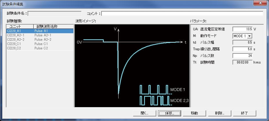
Waveform library for Ford EMC regulations (example)
 Pluse A1
- Pluse A2-1
- Pluse A2-2
- Pluse C-1
- Pluse C-2
 Pluse A1
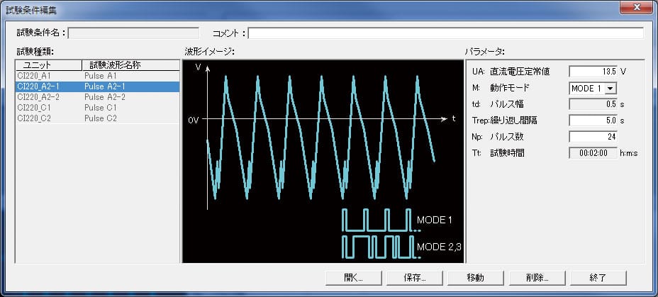 Pluse A2-1
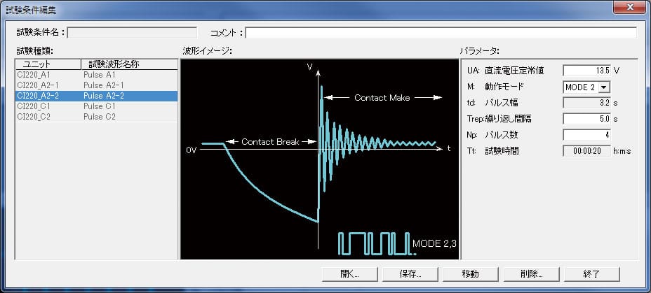 Pluse A2-2
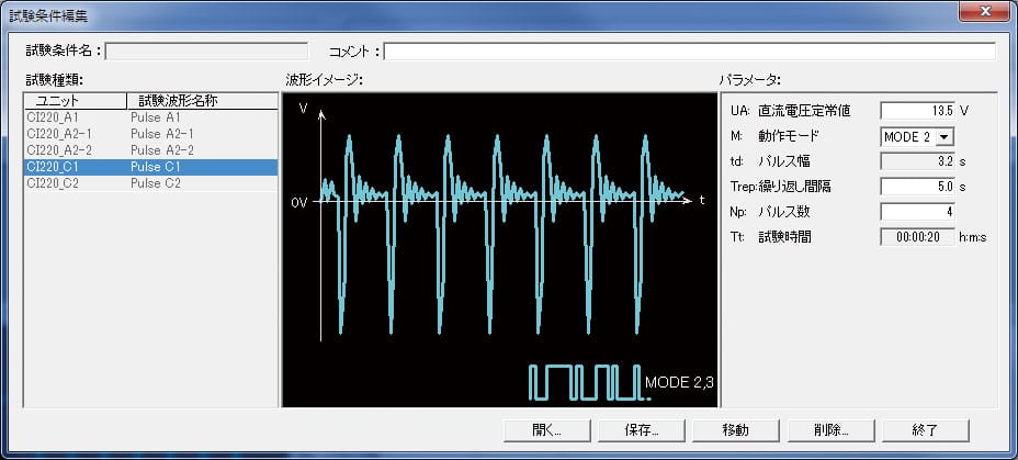 Pluse C-1
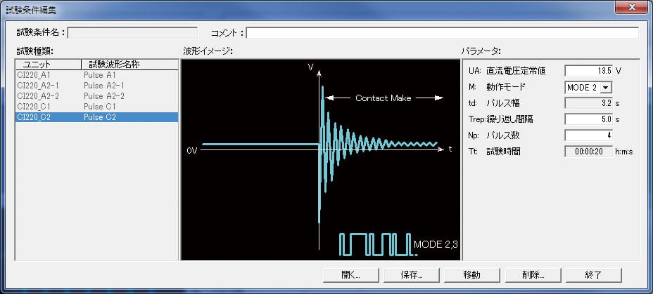 Pluse C-2
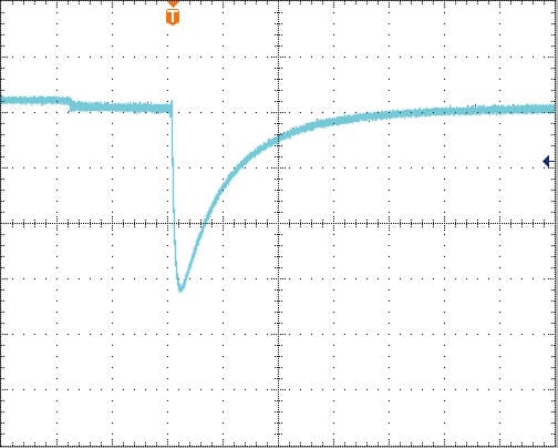
Output waveform (example)
 Pluse A1
 Pluse A2-1①
 Pluse A2-1②
 Pluse A2-2①
 Pluse A2-2②
 Pluse C-1
- Pluse C-2
 Pluse A1
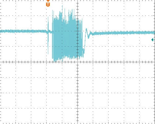 Pluse A2-1①
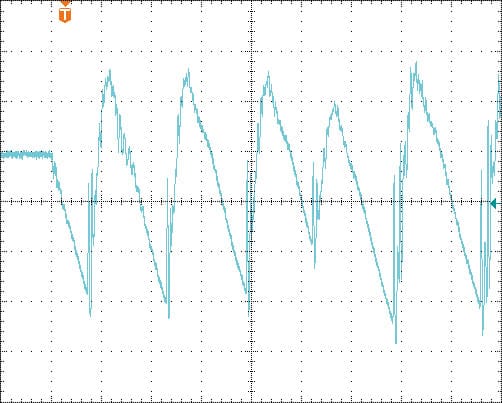 Pluse A2-1②
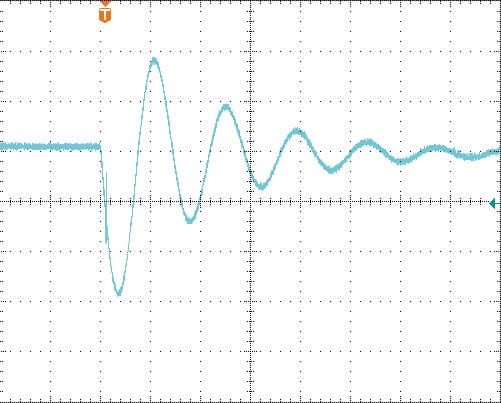 Pluse A2-2①
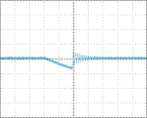 Pluse A2-2②
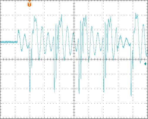 Pluse C-1
 Pluse C-2
Line-up
main frame

Pulse 1-12V/1-24V system


Pulse A1/12V system

Pulse module 2a system

Pulse module 3a/3b system
Pulse module 5a/5b system

Pulse 5b Load Dump Suppressor


Transient generator
Options
Series options. For more information on optional products, please refer to the individual product pages.


