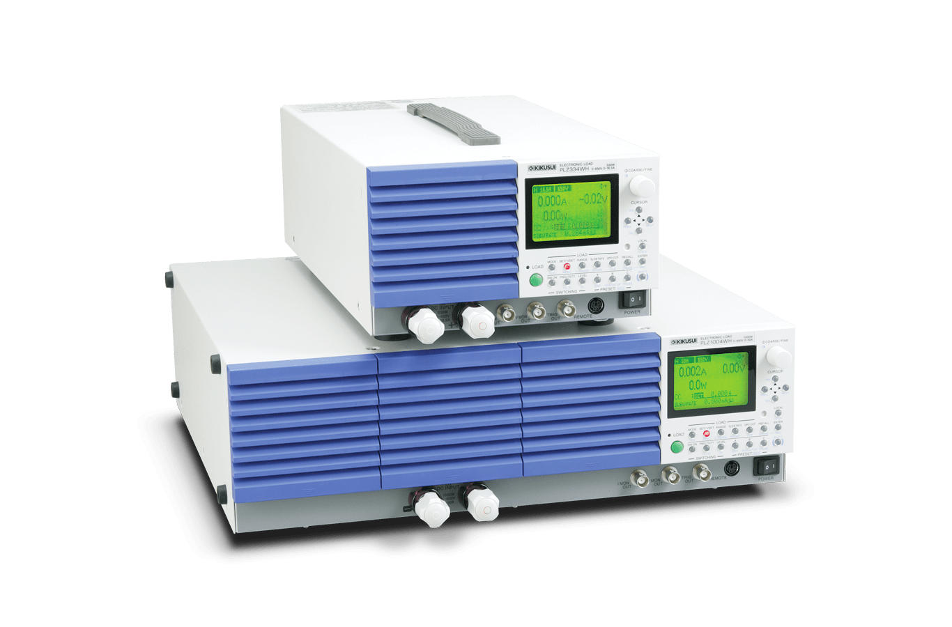
Multi-functional Electronic LoadPLZ-4WH Series
For EV and HEV high-voltage converters. With the booster, extended capacity at a low cost can be realized!
In recent years, the market trend of various devices that compose in the automotive electronics such as EV, HEV, and the new energy market for PV power generation, fuel cells, secondary batteries have been moved to higher voltage and larger capacities. At the same time, it has increased the demand for the Electronic Load evaluation equipment to meet these new requirement. The PLZ-4WH Series continues to provide excellent operability of the conventional model (PLZ-4W Series) while extending the maximum operating voltage to 650V. Furthermore, when a booster unit (PLZ2004WHB) is connected, up to 9kW/450A can be realized with less space and at a low cost. The interface, USB, GPIB, and RS232C functions comes as standard and supports automated testing applications.
Features
Supports high capacity
Achieving up to 9 kW/450 A with less space and low cost
By connecting the maximum of four PLZ2004WHB boosters (sold separately) to the PLZ1004WH, it is possible to use the product as an Electronic Load unit for up to 9 kW/450 A. Compared to parallel operation of the same model, size (space) reductions of up to about 30%, can be achieved. Incidentally, optional PC01-PLZ-4W and PC02-PLZ-4W parallel operation cables will be required for connections depend on the number of units to be connected.
Parallel operating units and capacity (maximum current and power)
[table id=1070 /]
Capable of parallel operation with up to five units of the same model
Parallel operation without the use of boosters is also possible up to five units of the same model, including the master unit, can be connected in parallel (5kW/250A maximum). In this case, the system operates under the master-slave configuration, and the master unit controls and displays the entire system. Note that optional PC01-PLZ-4W parallel operation cables will be required for connections depend on the number of units to be connected.
Parallel operating units and capacity (maximum current and power)
[table id=1071 /]
Reliable basic performance
Low range (1/100) feature
In CC, CR, and CP modes, three ranges are available: H, M, and L. The L range is 1/100, enabling coverage from low to high power with a single unit.
[table id=424 /]Ability to switch between a wide range of response speeds
The PLZ-4WH detects input current and voltage, and it operates by negative feedback control of those values. It secures and maintains stable operation by enabling the user to select the optimum speed of response by setting the negative feedback control response as shown below to counter operational instability that occurs in connection with the response characteristics of the test object, length of the load wiring, or size of the loop, for instance.
[table id=1072 /]Support for six operation modes
The PLZ-4WH is equipped with six operation modes: constant current, constant resistance, constant voltage, constant power, constant current + constant voltage, and constant resistance + constant voltage modes.

Load-on/off operations
Adopting the Load-on/off functions that flexibly apply to the system
With load-on/off operations, the following items can be selected in addition to standard operations:
- Start-up with load-on status when the power is turned on
- Display the elapsed time of the load-on period
- Load-off after a certain time has elapsed
- Load-on/off by the relay or other external signal
Soft start function
Assures even with steep voltage application
In constant current mode, the product can prevent the generation of overcurrent* even when voltage is steeply applied from the DUT in “Load On condition and with the current having been set.” For example, in a battery discharge test, it can suppress the generation of overcurrent when for some reason voltage is suddenly applied to an Electronic Load used for discharge.
*There is electrostatic capacitance between the Electronic Load input terminals. Charging and discharging current flows to this capacitance.
Ability to start up the power in CC mode
In many cases during constant voltage power supply tests, testing is conducted in constant resistance mode for start-up time measu- rements (during start-up), an d in co ns t ant cur rent mode during load change tests. If, however, the soft start time is set to a time corresponding to the start- up time of the cons tant voltage power supply, it is possible to perform start-up time measurements and load change tests in constant current mode, without changing the operation mode. (Either 1, 2, 5, 10, 20, 50, 100, or 200 ms can be selected as the soft start time.)
Sequence function
Actual load simulation by programming current waveforms internally
Arbitrarily set sequence patterns can be saved in the built-in memory and executed. Ten normal sequence programs and one fast sequence program can be saved. Although sequence editing and execution can be performed from the panel, those tasks can also be performed easily by using the application software separately sold “Wavy”* sequence creation software.
*A personal computer will require one of the following interfaces: USB, RS232C, or GPIB
Normal sequence
The execution time and Load ON/OFF can be set for each step. The level can be changed not only in a stepped form but also in a ramped form. It is also possible to cancel pausing both by using the PAUSE function and by external trigger input, and to synchronize with trigger output and other external equipment. 
Fast sequence
Each step is executed at high speed. Since the time resolution is high, fast simulation is possible. The execution time, level, and trigger output can be set.
Sequence configuration parameters
[table id=1073 /]Remote sensing function
Compensating the voltage drop of the wiring
Connecting a sensing terminal to the DUT makes it possible to set the combined resistance, including even the resistance of the wiring, from the panel in constant resistance mode. Also, points that connect the sensing function can be set to a certain power and certain voltage in constant power mode and constant voltage mode. Furthermore, since transient characteristics are improved in these constant voltage, constant power, and constant resistance modes, it also leads to operational stability. (Voltage that can be compensated: 2V one way)
Switching function
Transient response test conditions are also freely changeable on the spot
In constant current mode and constant resistance mode, switching operations of up to 4 kHz are possible with the built-in oscillator. Also, the level, frequency, duty cycle (ratio), and other configuration parameters can be changed even during a load-on period.
Short function
Improved efficiency for the current limit evaluation with a single action
In tests such as the DC power supply “fold-back type drooping charac teristics test of current limiting charac teristics,” the maximum current (in constant current mode) or the minimum resistance (in constant resistance mode) can be set with a single action and thus increase work efficiency. At the same time, since contact signals are output to an EXT CONT connector, it is possible to achieve even lower impedance shorting by driving exterior relays and shorting the output of the tested device.
Elapsed time display and automatic load-off timer
Convenient battery discharge function
 By combining four functions, namely, the elapsed time display, undervoltage protection (UVP), load-off voltage display, and automatic load-off timer, it is possible to perform two tests that are convenient for battery discharge testing, namely, the “measurement of time from discharge start to the final voltage” and “measurement from discharge start to the closed circuit voltage after a certain time has elapsed.”
ABC preset memory
Instantaneous retrieval of settings
Settings can be saved in three memories (A, B, and C) that are available for each range of each mode. Saved set tings can be freely retrieved and saved even during load-on periods. In constant current + constant voltage mode and constant resistance + constant voltage mode, the memories for the constant current and constant voltage, and for the constant resistance and constant voltage, can be retrieved and saved.
Protective functions and other features
Overcurrent protection (OCP), overpower protection (OPP), overvoltage protection (OVP), undervoltage protection (UVP), overheat protection (OHP), reverse connection protection (REV), external alarm input detection, configuration setting, and setup memories (100)
Applications
Evaluation Test on EV/HEV internal chargers and DC/DC converters

Built-in charger characteristics test and battery simulation

By connecting a DC Electronic Load unit and high-voltage DC power supply in parallel, the PLZ-4WH is used as a simulated battery for an EV in-vehicle charger. Start-up tests and load change tests are performed in Electronic Load CV mode.
Use as a high-speed constant-current power supply

The unit can be used as a high-speed constant-current power source by controlling high-speed positive current at A and negative current at B. A simulation of the regenerative current of brushless motor with regards to the interactive converter is performed.
For power supply variation tests

By connecting a DC Electronic Load unit and high-voltage DC power supply in parallel, the PLZ-4WH is used as a simulated battery to simulate medium speed power supply variations.Variation waveforms can be created and executed with Wavy sequence creation software.
For motor surge absorption measurement

During a brushless motor performance evaluation, the regenerative current from the brushless motor is absorbed, protecting the power supply and ECU.
For life performance acceleration tests

The PLZ-4WH can be used not only for temperature rise tests, long-term durability tests, pulse interrupt characteristics tests, and other high-accuracy constant current tests but also for pulse current evaluations.
As high-accuracy constant current power supply

By connecting a constant voltage power supply and a DC Electronic Load unit in series, the product achieves constant current at the DC Electronic Load unit’s constant current accuracy.
For battery charge-discharge tests

The PLZ-4WH can be used to evaluate impedance and residual capacity by discharging electricity not only at a normal constant current but also at a pulse current corresponding to the actual load. Waveform patterns can be created with Wavy for PLZ, too.
Battery capacitor

During a secondary cell performance evaluation, it is necessary to perform a capacity test based on the battery’s rating. Using the Electronic Load unit’s +CV function, a capacity evaluation is performed by discharging the CV when the prescribed voltage is reached.
Product line-up
Large Capacity Model SR(Smart Rack),LP(Load Pack)
PLZ-4WH SR/LP Series
PLZ-4WH SR/LP Series
The PLZ-4WH SR/LP Series offers wide range of the “Large-Capacity DC Electronic Load System” that consists of the conventional electronic load model PLZ1004WH and PLZ2004WHB applying to the high voltage (maximum 650V) installed in the exclusive rack mount system.
- The system offers from 5kW to 13kW with two types of rack system (SR/LP type), 12models are available.
- Assembled with exclusive components based on optimization design concept. Delivers the system with fully assembled and tested, so immediate operation is possible.
- The industry’s smallest in its class for the multi-functional high-speed response DC electronic load.
- Expandable by installing additional booster units after purchase.*For the installation, adjustment, please contact your nearest distributor.
- AC Input 90 to 250Vac Auto select, less than 1A. No special wiring is required.
- Range switching function allows to guarantee the specificatiosn even for the samller capacity input. (Perfromance test Data is included with the system as standard document)
- Equipped USB/RS232C/GPIB interface as standard features.
- Capable of operation using the Sequence Creation software “Wavy”.
- The Load input terminal is designed on the Safety-Comes-First concept. (protection against electric shocks)
- Load cable for large current is available as option. (50A/100A/200A/500A/1000A, 3m, the cable equipped with solderless terminals on both ends)
- The base hold angle for fixing the anchor bolt (OP03-KRC) is available as a rack mount option.