

Battery Emulator System for PXB
Battery Emulator System
価格お問い合わせ
- Battery emulation is possible based on CV mode
- Auto-completion function automatically generates missing I-V characteristic data
- Battery characteristics correspond to I-V data (3D IV-table) for each SOC
- Definable SOC or capacity at start of operation
- Setting range of SOC for stop condition is possible
- Display I-V curve graph for each SOC
- Display measurements and graphs in real time
| Image | SKU | Output Power [W] | Output CV [V] | Output CC [A] | 標準価格 | WEBかんたんお見積り |
|---|---|---|---|---|---|---|
 | BATTERY EMULATOR SYSTEM PXB20K-50 | 20kW | 50V | -800A to +800A | オープン価格(お問い合わせください) | |
| BATTERY EMULATOR SYSTEM PXB20K-250 | 20kW | 250V | -200A to +200A | オープン価格(お問い合わせください) | |
| BATTERY EMULATOR SYSTEM PXB20K-500 | 20kW | 500V | -120A to +120A | オープン価格(お問い合わせください) | |
| BATTERY EMULATOR SYSTEM PXB20K-1000 | 20kW | 1000V | -60A to +60A | オープン価格(お問い合わせください) | |
| BATTERY EMULATOR SYSTEM PXB20K-1500 | 20kW | 1500V | -30A to +30A | オープン価格(お問い合わせください) |
Line-up
| Image | Model | Output | Other | ||||
|---|---|---|---|---|---|---|---|
| CV | CC | Rated power | Input current AC (200 V 3-phase) / (400 V 3-phase) | Weight (Approx.) | |||
| BATTERY EMULATOR SYSTEM PXB20K-50 | 50V | ±800A | ±20kW | 80/40A | 41kg | |
| BATTERY EMULATOR SYSTEM PXB20K-250 | 250V | ±200A | ±20kW | 80/40A | 39kg | |
| BATTERY EMULATOR SYSTEM PXB20K-500 | 500V | ±120A | ±20kW | 80/40A | 38kg | |
| BATTERY EMULATOR SYSTEM PXB20K-1000 | 1000V | ±60A | ±20kW | 80/40A | 37kg | |
| BATTERY EMULATOR SYSTEM PXB20K-1500 | 1500V | ±30A | ±20kW | 80/40A | 37kg | |
Features
A simple battery emulator achieved with the PXB Series bidirectional high-capacity DC power supply and application software
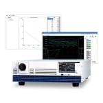
The battery emulator system is constructed by combining the PXB Series bidirectional high-capacity DC power supply and the SD036-PXB application software. Based on the preset I-V characteristic data, it is possible to simulate the charging and discharging operation of the battery. Since the voltage value is changed in real time according to the SOC and current value, and the behavior close to that of an actual battery can be reproduced, it is possible to repeatedly execute tests under certain conditions that are difficult with an actual battery.
System Configuration
Connect via LAN or USB; LAN connection can also be made via a hub.


Required System Configuration
- Core i5 or higher
- Windows 11 or Windows 10(x64)
- 8 GB or more RAM
- Hard disk with 10 GB or more free space
- Displays supporting an image resolution of 1366 x 768 (FWXGA) or more
- mouse
- USB*1 or LAN (depending on interface used)
- KI-VISA Library 5.5.0 or more
- USB dongle key
*1 One port is required to connect a USB dongle key.
Test Preparation & Procedures
The ability to reproduce specific battery conditions through configuration allows for repeated testing under conditions that are difficult to achieve with real batteries.
Base I-V File Required
Battery Emulator requires a base I-V file (CSV format) on which to base the emulation.
Example of Base I-V File Creation


Useful complementary functions ➀ Current value
If the Current values in the base I-V file are further apart than 0.1A before and after, the data between the two points is filled in by linear interpolation, generating current and voltage value data every 0.1A.


![]()
I-V table seat
Imports I-V characteristics data for each SOC; I-V characteristics data can be imported for 10 or more points of Current and Voltage data, up to a maximum of 1000 points.
Useful completion functions➁ SOC value
When the initial numerical values (SOC values) in the base I-V file are more than 1% apart, interpolation I-V files are generated at 1% intervals by evenly dividing the difference into 1% increments.


![]()
Emulation Condition Setting Screen
Set battery specs/battery condition.


![]()
Test Execution Screen
When operation is started, the interpolated I-V file to be simulated is selected and the operating points of the control are plotted in orange.


Specifications
Output rating
| Item | BATTERY EMULATOR SYSTEM PXB20K-50 | BATTERY EMULATOR SYSTEM PXB20K-250 | BATTERY EMULATOR SYSTEM PXB20K-500 | BATTERY EMULATOR SYSTEM PXB20K-1000 | BATTERY EMULATOR SYSTEM PXB20K-1500 |
|---|---|---|---|---|---|
| Rated power | ±20000 W | ±20000 W | ±20000 W | ±20000 W | ±20000 W |
| Rated voltage (source) *1 | 0 V to 50 V | 0 V to 250 V | 0 V to 500 V | 0 V to 1000 V | 0 V to 1500 V |
| Operating voltage (sink) *2 | 3 V to 50 V | 15 V to 250 V | 10 V to 500 V | 20 V to 1000 V | 30 V to 1500 V |
| Rated current *1 | ±800 A | ±200 A | ±120 A | ±60 A | ±30 A |
*1. Limited by the maximum output power. *2. Operating voltage at which the rated sink current can be applied.
Output voltage
| Item | BATTERY EMULATOR SYSTEM PXB20K-50 | BATTERY EMULATOR SYSTEM PXB20K-250 | BATTERY EMULATOR SYSTEM PXB20K-500 | BATTERY EMULATOR SYSTEM PXB20K-1000 | BATTERY EMULATOR SYSTEM PXB20K-1500 | ||
|---|---|---|---|---|---|---|---|
| Maximum settable voltage | 52.5 V | 262.5 V | 525 V | 1050 V | 1575 V | ||
| Setting accuracy | ±(0.2 % of setting + 0.1 % of rating) | ||||||
| Resolution | 0.005 V | 0.02 V | 0.05 V | 0.1 V | 0.1 V | ||
| Power fluctuation*1 | ±10 mV | ±50 mV | ±100 mV | ±200 mV | ±300 mV | ||
| Load variation*2 | ±40 mV | ±125 mV | ±250 mV | ±500 mV | ±750 mV | ||
| Remote sensing Maximum compensation voltage (reciprocating) | 10 % of rating | ||||||
| Internal resistance setting upper limit | 63 mΩ | 1575 mΩ | 5250 mΩ | 21000 mΩ | 63000 mΩ | ||
| Internal resistance setting resolution | 1 mΩ | 1 mΩ | 1 mΩ | 2 mΩ | 5 mΩ | ||
| Response switching | FAST, SLOW | ||||||
| Slew rate switching (TYP) | 12.5 V/ms or more *3 | 62.5 V/ms or more *3 | 125 V/ms or more *3 | 250 V/ms or more *3 | 375 V/ms or more *3 | ||
| 12.5 V/ms | 62.5 V/ms | 125 V/ms | 250 V/ms | 375 V/ms | |||
| 1.25 V/ms | 6.25 V/ms | 12.5 V/ms | 25.0 V/ms | 37.5 V/ms | |||
| 0.125 V/ms | 0.625 V/ms | 1.25 V/ms | 2.50 V/ms | 3.75 V/ms | |||
| 0.0125 V/ms | 0.0625 V/ms | 0.125 V/ms | 0.250 V/ms | 0.375 V/ms | |||
| Source only *4 | Transient response *5 | 8 ms or less | 8 ms or less | 8 ms or less | 10 ms 以下 | 10 ms 以下 | |
| Ripple noise *6 | p-p*7 | 250 mV | 375 mV | 1000 mV | 1500 mV | 2500 mV | |
| rms*8 | 30 mV | 125 mV | 250 mV | 500 mV | 750 mV | ||
| Rise time *9 | Full load *10 | 10 ms | |||||
| No load | 10 ms | ||||||
| Fall time *11 | Full load *10 | 10 ms | |||||
| No load | 10 ms | ||||||
*1. 180 Vac to 252 Vac for 200 Vac input, 342 Vac to 504 Vac for 400 Vac input. At the constant load. *2. The amount of change that occurs when the load is changed from no load to full load (rated output power/rated output voltage) with rated output voltage. The value is measured at the sensing point. *3. MAX will appear on the display. *4. In the case that the CV mode response setting is set to FAST. *5. The amount of time required for the output voltage to return to a value within “rated output voltage ±(0.1 % + 10 mV).” The load current fluctuation is 50 % to 100 % of the maximum current with the set output voltage. *6. At the rated output current. Values measured using JEITA RC-9131C probe and 100:1 probe. *7. Measurement frequency band: 10 Hz to 20 MHz *8. Measurement frequency band: 10 Hz to 1 MHz *9. 10 % to 90 % of the rated output voltage. *10.For a pure resistance. *11. 90 % to 10 % of the rated output voltage.
Output current
| Item | BATTERY EMULATOR SYSTEM PXB20K-50 | BATTERY EMULATOR SYSTEM PXB20K-250 | BATTERY EMULATOR SYSTEM PXB20K-500 | BATTERY EMULATOR SYSTEM PXB20K-1000 | BATTERY EMULATOR SYSTEM PXB20K-1500 |
|---|---|---|---|---|---|
| Settable maximum source current | +840 A | +210 A | +126 A | +63 A | +31.5 A |
| Settable maximum sink current | -840 A | -210 A | -126 A | -63 A | -31.5 A |
| Seamless setting current range | -840 A to +840 A | -210 A to +210 A | -126 A to +126 A | -63 A to +63 A | -31.5 A to +31.5 A |
| Setting accuracy | ±(0.75 % of rating) | ||||
| Resolution | 0.1 A | 0.02 A | 0.01 A | 0.005 A | 0.002 A |
| Line regulation | ±1600 mA | ±400 mA | ±240 mA | ±120 mA | ±60 mA |
| Load regulation | ±1600 mA | ±400 mA | ±240 mA | ±120 mA | ±60 mA |
| Rise time (Short-circuit) (TYP) *1 | 5 ms | ||||
| Fall time (Short-circuit) (TYP) *2 | 5 ms | ||||
| Charge/discharge switching time (TYP) | 10 ms | ||||
| Response switching | FAST, SLOW | ||||
| Slew rate switching (TYP) | 200 A/ms or more*3 | 50 A/ms or more *3 | 30 A/ms or more*3 | 15 A/ms or more *3 | 7.5 A/ms or more *3 |
| 200 A/ms | 50 A/ms | 30 A/ms | 15 A/ms | 7.5 A/ms | |
| 20 A/ms | 5 A/ms | 3 A/ms | 1.5 A/ms | 0.75 A/ms | |
| 2 A/ms | 0.5 A/ms | 0.3 A/ms | 0.15 A/ms | 0.075 A/ms | |
| 0.2 A/ms | 0.05 A/ms | 0.03 A/ms | 0.015 A/ms | 0.0075 A/ms | |
*1. In the case that the CC mode response setting is set to FAST: Applied in response to changes from 10 % to 90 % of rated output current. *2. In the case that the CC mode response setting is set to FAST: Applied in response to changes from 90 % to 10 % of rated output current. *3. MAX will appear on the display.
Output power
| Item | Common to all models |
|---|---|
| Settable maximum source power | +21000 W |
| Settable maximum sink power | -21000 W |
| Seamless setting power range | -21000 W to +21000 W |
| Setting accuracy *1 | ±(0.5 % of power rating + 0.5 % of current rating × Vout) |
| Resolution | 2 W |
*1. Equal to or higher than 5 % of the rated power is guaranteed. Less than 5 % of the rated power is guaranteed as a TYP value.
200 V three-phase three-wire input
| Item | Common to all models |
|---|---|
| Nominal input rating | 200 Vac to 240 Vac, 50 Hz to 60 Hz |
| Input voltage range | 180 Vac to 252 Vac |
| Input frequency range | 47 Hz to 63 Hz |
| Input current (MAX)*1 | 80 A (180 V) |
| Input power (MAX)*1 | 24 kVA |
| Inrush current (TYP)*2 | 90 A |
| Power factor (TYP)*1 | 0.96 |
| Output hold time | 10 ms or more |
*1. At the rated output power for the rated output current. *2. Maximum peak current value when the POWER switch is turned on. (Excluding the surge current to the input filter capacitor.)
400 V three-phase three-wire input
| Item | Common to all models |
|---|---|
| Nominal input rating | 380 Vac to 480 Vac, 50 Hz to 60 Hz |
| Input voltage range | 342 Vac to 504 Vac |
| Input frequency range | 47 Hz to 63 Hz |
| Input current (MAX)*1 | 40 A (342 V) |
| Input power (MAX)*1 | 24 kVA |
| Inrush current (TYP)*2 | 70 A |
| Power factor (TYP)*1 | 0.96 |
| Output hold time | 10 ms or more |
*1. At the rated output power for the rated output current. *2. Maximum peak current value when the POWER switch is turned on. (Excluding the surge current to the input filter capacitor.)
Display
| Item | BATTERY EMULATOR SYSTEM PXB20K-50 | BATTERY EMULATOR SYSTEM PXB20K-250 | BATTERY EMULATOR SYSTEM PXB20K-500 | BATTERY EMULATOR SYSTEM PXB20K-1000 | BATTERY EMULATOR SYSTEM PXB20K-1500 | |
|---|---|---|---|---|---|---|
| Voltmeter | Maximum display | ±60.000 V | ±300.00 V | ±600.00 V | ±1200.00 V | ±1800.00 V |
| Display accuracy | ±(0.1 % of reading + 0.2 % of rating) | |||||
| Ammeter | Maximum display | ±1120.000 A | ±336.000 A | ±168.000 A | ±84.000 A | ±42.000 A |
| Display accuracy | ±(0.75 % of rating) | |||||
| Wattmeter | Maximum display *1 | ±24.000 kW | ||||
| Display accuracy | Display the integrated value of voltmeter and ammeter | |||||
| Operation display | Output ON / OFF | The OUTPUT LED on the front panel lights in green | ||||
| Operation mode | Indicate the followings on the upper left part of the display | |||||
| CV: CV icon | ||||||
| CC: CC icon | ||||||
| CP: CP icon | ||||||
| Remote (LAN) | Indicate the followings on the upper left part of the display | |||||
| Not connected: Red LAN icon | ||||||
| Preparing for connection: Orange LAN icon | ||||||
| Connected: Green LAN icon | ||||||
| Alarm | Indicate the details of activated protection function on the display | |||||
| SCPI error | Indicate the error occurring at present on the display | |||||
| POWER off | Indicate residual charge warning and an instruction to turn off the display, then reboot | |||||
| key lock | Indicate the key lock status on the upper right part of the display | |||||
| Sensing | When sensing is enabled, indicate the sensing icon on the upper right part of the display | |||||
| During parallel operation | Displaying the slave state on the slave unit | |||||
| External control | When digital input/output is enabled, indicate the EXT icon on the upper right part of the display | |||||
*1 The unit will be W if it is less than 10 kW.
Protection function LOW alarm An alarm not requiring a reboot to be cleared.
| Item | BATTERY EMULATOR SYSTEM PXB20K-50 | BATTERY EMULATOR SYSTEM PXB20K-250 | BATTERY EMULATOR SYSTEM PXB20K-500 | BATTERY EMULATOR SYSTEM PXB20K-1000 | BATTERY EMULATOR SYSTEM PXB20K-1500 | |
|---|---|---|---|---|---|---|
| OVP (Over Voltage Protection) | Protective operation | Output off, indicate “OVP” on the display. SLV OVP is displayed on the slave unit. | ||||
| Setting range | 5 V to 55 V | 25 V to 275 V | 50 V to 550 V | 100 V to 1100 V | 150 V to 1650 V | |
| Setting accuracy | ±(0.1 % of setting + 0.2 % of rating) | |||||
| Resolution | 0.005 V | 0.02 V | 0.05 V | 0.1 V | 0.1 V | |
| OCP (Over Current Protection) | Protective operation | Output off, indicate “OCP” on the display. SLV OCP is displayed on the slave unit. | ||||
| Setting range (Source) | 80 A to 880 A | 20 A to 220 A | 12 A to 132 A | 6 A to 66 A | 3 A to 33 A | |
| Setting range (Sink) | -80 A to -880 A | -20 A to -220 A | -12 A to -132 A | -6 A to -66 A | -3 A to -33 A | |
| Setting accuracy | ±(0.75 % of rating) | |||||
| Resolution | 0.1 A | 0.02 A | 0.01 A | 0.005 A | 0.002 A | |
| OPP (Over Power Protection) | Protective operation | Output off, indicate “OPP” on the display. SLV OPP is displayed on the slave unit. | ||||
| Setting range (Source) | 2 kW to 24 kW | |||||
| Setting range (Sink) | -2 kW to -24 kW | |||||
| Setting accuracy | ±(1.0 % of power rating +1.0 % of current rating × Vout) | |||||
| Resolution | 2 W | |||||
| UVP (Under Voltage Protection) | Protective operation | Output off, indicate “UVP” on the display. SLV UVP is displayed on the slave unit. | ||||
| Setting range | 0 V to 50 V | 0 V to 250 V | 0 V to 500 V | 0 V to 1000 V | 0 V to 1500 V | |
| Selectable | Enable/Disable | |||||
| Setting accuracy | ±(0.1 % of setting + 0.2 % of rating) | |||||
| Resolution | 0.005 V | 0.02 V | 0.05 V | 0.1 V | 0.1 V | |
| Watchdog Alarm (Communication error protection) | Protective operation | Output off, indicate “WDOG” on the display | ||||
| Setting range | 1 s to 3600 s | |||||
| Selectable | Enable/Disable | |||||
| External Alarm LOW Level (external input alarm detection) | Protective operation | Output off, indicate “EXT LOW” on the display | ||||
Protection function HIGH alarm An alarm requiring a reboot to be cleared.
| Item | Common to all models | |
|---|---|---|
| Reverse Alarm (Reverse-connection detection protection) | Protective operation | Output off, indicate “REVE” on the display |
| OHP (Overheat protection) | Protective operation | Output off, indicate “OHP” on the display. SLV OHP is displayed on the slave unit. |
| Line OVP (Grid overvoltage protection) | Protective operation | Output off, indicate “LOVP” on the display. SLV LOVP is displayed on the slave unit. |
| Setting range | Input voltage rating 200 Vac model: 200 V to 258 V Input voltage rating 400 Vac model: 380 V to 516 V | |
| Line UVP (Grid undervoltage protection) | Protective operation | Output off, indicate “LUVP” on the display. SLV LUVP is displayed on the slave unit. |
| Setting range | Input voltage rating 200 Vac model: 175 V or less. Input voltage rating 400 Vac model: 333 V or less. | |
| Line Frequency Error (Grid abnormal frequency protection) | Protective operation | Output off, indicate “FREQ” on the display. SLV FREQ is displayed on the slave unit. |
| Detection value | 42 Hz/68 Hz | |
| External Alarm HIGH Level (External input alarm detection) | Protective operation | Output off, indicate “EXT HIGH” on the display |
| SENS Alarm (incorrect sensing connection detection) | Protective operation | Output off, indicate “SENS” on the display |
| Setting range | Enable/Disable | |
| Parallel Communication Error (Parallel operation communication error detected) | Protective operation | Output off, indicate “PARA COM” on the display |
| Para Other Slave Alarm (Parallel operation slave error occurred) | Protective operation | Output off, indicate “SLV OTHR” on the display |
| Incorrect Slave Alarm (Not applicable device connected) | Protective operation | Output off, indicate “SLV INC” on the display |
| Too many connections (Too many parallel connections) | Protective operation | Output off, indicate “TOO MANY” on the display |
| Hardware ERR *1 (Hardware error) | Protective operation | Output off, indicate “ERRH” on the display. SLV ERRH is displayed on the slave unit. |
| Software ERR *2 (Software error) | Protective operation | Output off, indicate “ERRS” on the display. SLV ERRS is displayed on the slave unit. |
*An alarm requiring a reboot to be cleared. *1. It occurs when an abnormality related to the hardware is detected and the internal unit comes to an emergency stop. *2. It occurs when an abnormality related to the software is detected and the internal unit comes to an emergency stop.
External analog I/O
| Item | Common to all models | ||
|---|---|---|---|
| Input | Input points | 2 points | |
| Voltage (CV) control | Setting range | 0 % to 100 % of the rated output voltage | |
| Input voltage range | 0 V to +5 V or 0 V to +10 V (Selectable) | ||
| Accuracy | ±(1 % of rating) | ||
| Current (CC) control Power (CP) control *1 | Setting range | −100 % to +100 % of the rated current and rated power | |
| Input voltage range | −5 V to +5 V or −10 V to +10 V (Selectable) | ||
| Accuracy | ±(1 % of rating) | ||
| Output | Output points | 2 points | |
| Voltage monitor (VMON) | Monitor range | 0 % to 100 % of the rated output voltage | |
| Output voltage range | 0 V to +5 V or 0 V to +10 V (Selectable) | ||
| Accuracy | 1 % of rating | ||
| Current monitor (IMON) | Monitor range | −100 % to +100 % of the rated output voltage | |
| Output voltage range | −5 V to +5 V or −10 V to +10 V (Selectable) | ||
| Accuracy | ±(1 % of rating) | ||
*1 Select either current control or power control.
External digital input
| Item | Common to all models | |
|---|---|---|
| Fixed input points | 1 point (Polarity switchable) | |
| Selected input points | 5 points (Polarity switchable) | |
| Input form | Photocoupler isolated input (Applicable to both current sink / source output) | |
| Fixed function | ALARM IN | HIGH alarm occurrence |
| Selecting function | OFF | Do not use terminals |
| OUTPUT ON | Turn on the output | |
| OUTPUT OFF | Turn off the output | |
| OUTPUT CTRL | Turn on of off the output | |
| L ALARM IN | LOW alarm occurrence | |
| ALARM CLR | LOW alarm clearance | |
| SEQ RUN | Sequence start/end | |
| SEQ PAUSE | Sequence pause/resume | |
| INTEG CTRL | Starting/stopping integration measurement | |
| INTEG RESET | Resetting integration measurement data | |
| ACQUIRE TRIG | Input the measurement trigger | |
| SEQ TRIG IN | Input the trigger for sequence | |
| MEM1 RECALL | Recall preset memory 1 | |
| MEM2 RECALL | Recall preset memory 2 | |
| External circuit power supply range | 12 V to 24 Vdc (±10 %) | |
External digital output
| Item | Common to all models | |
|---|---|---|
| Output points | 6 points (Polarity switchable) | |
| Output form | Semiconductor relay output | |
| Selecting function | OFF | Do not use terminals |
| OUTPUT ON | Outputting the signal while the output is ON | |
| POWER ON | Signal is output when power supply is on and output is possible | |
| H ALARM OUT | Output a signal when a HIGH alarm occurs | |
| L ALARM OUT | Output a signal when a LOW alarm occurs | |
| CC STATUS | Output a signal when operating in the CC mode | |
| CV STATUS | Output a signal when operating in the CV mode | |
| SEQ TRIG OUT | Output the trigger for sequence | |
| SEQ STATUS | Signal is output while the sequence is running | |
| EXT DIN BUSY | Output a signal when the digital input is in BUSY status | |
| MEM1 ACT TIME | Signal is output when the setting is completed for preset memory 1 | |
| MEM2 ACT TIME | Signal is output when the setting is completed for preset memory 2 | |
| RELAY DRIVE | Output a signal after approx. 100 ms in step with on/off of the DC OUTPUT terminal output. You can set this parameter to only Ch.6. | |
Communication interface
| Item | Common to all models | |
|---|---|---|
| Common specifications | Software protocol | IEEE std. 488.2-1992 |
| Command language | Complies with SCPI Specification 1999.0 | |
| RS232C | Hardware | D-SUB 9-pin connector Baud rate: 1200, 2400, 4800, 9600, 19200, 38400, 57600, 115200 bps Data length: 8 bits, Stop bits: 1 bit, Parity bit: None Flow control: No, CTS-RTS |
| Program message terminator | LF during reception, LF during transmission. | |
| USB (device) | Hardware | Standard type B socket. Complies with the USB 2.0 specifications; data rate: 480 Mbps (high speed) |
| Program message terminator | LF or EOM during reception, LF + EOM during transmission | |
| Device class | Complies with the USBTMC-USB488 device class specifications | |
| USB (host) | Hardware | Standard type A socket. Complies with the USB 2.0 specifications; data rate: 480 Mbps (high speed) |
| LAN | Hardware | IEEE 802.3 100BASE-TX or 10BASE-T Ethernet |
| Communication protocol | SCPI-RAW, SCPI-Telnet, HiSLIP, VXI-11 | |
| Program message terminator | SCPI-RAW: LF during reception, LF during transmission HiSLIP: LF or END during reception, LF + END during transmission. | |
| Compliant standards | LXI Version 1.5 Specifications 2016 | |
Others
| Item | Common to all models | ||
|---|---|---|---|
| Synchronization function (clock synchronization) | Overview | SYNC icon is displayed on the display when synchronization is established with the internal clock after connecting with other PXB series using the EXT SYNC connector. | |
| Sequence synchronization | Synchronization of the program start and step start. | ||
| Measurement synchronization | Synchronization of the measurement start | ||
| Output synchronization | Synchronization of output ON/OFF | ||
| Sequence function | Operation mode | CV, CC, and CP modes | |
| Maximum number of programs | 30 | ||
| Maximum number of steps | 10000 | ||
| Step execution time | 1 ms to 3600 000 s | ||
| Loop count | 1 to 100000, or infinite | ||
| Sine Function | Operation mode | CV/CC mode | |
| Frequency setting range | 1 Hz to 1000 Hz | ||
| Frequency resolution | 1 Hz to 10 Hz | 0.2 Hz | |
| 12 Hz to 100 Hz | 2 Hz | ||
| 120 Hz to 1000 Hz | 20 Hz | ||
| CV | Maximum setting | Setting range up to 105 % of rated voltage | |
| Maximum offset setting | Setting range up to 105 % of rated voltage | ||
| CC | Maximum setting | Setting range up to 210 % of rated current | |
| Maximum offset setting | Setting range up to ±105 % of rated current | ||
| Pulse function | Operation mode | CV/CC mode | |
| Frequency setting range | 1 Hz to 1000 Hz | ||
| Frequency resolution | 1 Hz to 10 Hz | 0.01 Hz | |
| 12 Hz to 100 Hz | 0.1 Hz | ||
| 120 Hz to 1000 Hz | 1 Hz | ||
| CV | High level rated current | Setting range up to 105 % of rated voltage | |
| Low level rated current | Setting range up to 105 % of rated voltage | ||
| CC | High level rated current | Setting range up to 105 % of rated current | |
| Low level rated current | Setting range up to 105 % of rated current | ||
| Duty cycle | 2.5 % to 97.5 % | ||
| Measurement trigger | Measurement start condition (trigger source) | Conditions for starting measurement can be selected (when inputting from display, when inputting commands by remote control, when inputting signals by external control, and when operating in synchronization) | |
| Number of measurements | 1 to 65536 | ||
| Measurement delay time | Setting range | 0 s to 100 s | |
| Resolution | 0.1 ms | ||
| Measurement interval | Setting range | 0.1 ms to 3600 s | |
| Resolution | 0.1 ms | ||
| Measurement time | Setting range | 0.1 ms to 1 s | |
| Resolution | 0.1 ms | ||
| I-V characteristic function | Operation mode | CV/CC mode | |
| Number of setup items | 3 to 100 items (interpolated between points with straight lines) | ||
| Preset memory | Number of memory entries | 20 | |
| Saved setting | Values in CV, CC, and CP modes, protection function values, and IR values | ||
| Setup Memory | Number of memory entries | 21 | |
| Saved setting | On/off of the output from the DC OUTPUT terminal, Output voltage value/Output current value/Output power value, Output current for seamless operation (DC SEAM), Output mode, Response, Slew Rate, Priority operation mode (Priority when output is ON), Impedance Setting When the Output is Off (Impedance when output is OFF), Value of the pulse function (Duty, Frequency, High, Low), Value of the sine function (Amplitude, Frequency, Offset), Number of I-V characteristics (Count), Internal resistance value (IR), Over voltage protection (OVP), Under voltage protection (UVP, UVP Enable), Over current protection (OCP(+), OCP(-), Delay), Over power protection (OPP(+), OPP(-)), Line overvoltage protection (Line OVP), Measurement trigger settings (Source, Count, Delay, Enable, Timer), Integration settings (Gate, Reset) | ||
| key lock | Level 1 | Output on/off and preset memory recall are available | |
| Level 2 | Output on/off are available | ||
| Level 3 | Output off is available | ||
| Number of parallel operated load modules | Up to 25 units | ||
General Specifications
| Item | BATTERY EMULATOR SYSTEM PXB20K-50 | BATTERY EMULATOR SYSTEM PXB20K-250 | BATTERY EMULATOR SYSTEM PXB20K-500 | BATTERY EMULATOR SYSTEM PXB20K-1000 | BATTERY EMULATOR SYSTEM PXB20K-1500 | |
|---|---|---|---|---|---|---|
| Weight | Approx. 41 kg (90.39 lbs) | Approx. 39 kg(85.98 lbs) | Approx. 38 kg (83.78 lbs) | Approx. 37 kg (81.57 lbs) | Approx. 37 kg (81.57 lbs) | |
| Dimensions | 430 (16.93)W×128 (5.04)H×720 (28.35)Dmm (inches) For details, refer to the dimensional drawing. | |||||
| Environmental conditions | Operating environment | Indoor use, overvoltage category II | ||||
| Operating temperature | 0 °C to +40 °C (32 °F to +104 °F) | 0 °C to +50 °C (32 °F to +122 °F) | ||||
| Operating humidity | 20 % rh to 85% rh (no condensation) | |||||
| Storage temperature | −25°C to +60°C (−13 °F to +140 °F) | |||||
| Storage humidity | 90 % rh or less (no condensation) | |||||
| Altitude | Up to 2000m | |||||
| Cooling method | Forced air cooling using fan | |||||
| Accessories | Input terminal cover, External control connector kit (1 set), Chassis connection wire, OUTPUT terminal cover, DC OUTPUT terminal screws (1 pair), EXT SYNC connector cover, SENSING connector cover, SENSING connector (2 pc.), Synchronized operation signal cable kit, Safety Information (1 copy), China RoHS sheet (1 sheet), Getting Started Guide (1 copy), Heavy object warning label (1 pc.) | |||||
| Withstanding voltage | Between input and GND | 2200 Vac for 1 minute | ||||
| Between input and output | ||||||
| Between output and GND | 500 Vdc for 1 minute | 1000 Vdc for 1 minute | 1800 Vdc for 1 minute | 1800 Vdc for 1 minute | 3000 Vdc for 1 minute | |
| Insulation resistance | Between input and GND | 30 MΩ, 500 Vdc | ||||
| Between input and output | 30 MΩ, 500 Vdc | 30 MΩ, 600 Vdc | 30 MΩ, 1000 Vdc | |||
| Isolation voltage | ±250 V | ±600 V | ±1000 V | ±1000 V | +2000 V/−1000 V | |
| Electromagnetic compatibility (EMC) *1*2 | Complies with the requirements of the following directive and standards. EMC Directive 2014/30/EU EN 61326-1 (Class A*3) | |||||
| Safety*1 | Complies with the requirements of the following directive and standards. Low Voltage Directive 2014/35/EU*2 EN 61010-1 (Class I*4, Overvoltage category II, Pollution Degree 2*5) | |||||
*1. Does not apply to specially ordered or modified products. *2. Only for models with CE marking / UKCA marking on their body. *3. This is a Class A instrument. This product is intended for use in an industrial environment. This product may cause interference if used in residential areas. Such use must be avoided unless the user takes special measures to reduce electromagnetic emissions to prevent interference to the reception of radio and television broadcasts. *4. This is a Class I instrument. Be sure to ground this product’s protective conductor terminal. The safety of this product is guaranteed only when the product is properly grounded. *5. Pollution is addition of foreign matter (solid, liquid or gaseous) that may produce a reduction of dielectric strength or surface resistivity. Pollution Degree 2 assumes that only non-conductive pollution will occur except for an occasional temporary conductivity caused by condensation.
Options
Load cable
Compatible model: BATTERY EMULATOR SYSTEM PXB20K-50

Compatible models: BATTERY EMULATOR SYSTEM PXB20K-250、BATTERY EMULATOR SYSTEM PXB20K-500
Compatible models: BATTERY EMULATOR SYSTEM PXB20K-1000, BATTERY EMULATOR SYSTEM PXB20K-1500


