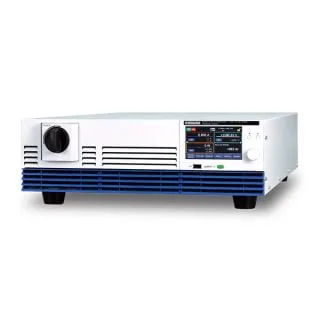
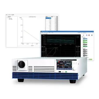
Bidirectional
High-Capacity
DC Power Supplies
PXB Series
Condenses a 20 kW large-capacity output
into a 3U-size chassis.
Condenses a 20 kW large-capacity output
into a 3U-size chassis.
Not only handling high voltages of 1500 V, but also capable of both power and regeneration in both directions in a single unit.
We provide a new power supply test environment for electrical and electronic equipment that is becoming increasingly high-powered.
In addition, a variety of analog, digital, and communication interfaces are provided for optimal operation at any stage of research, development, and manufacturing! A new generation of bidirectional DC power supplies that support the progression of advanced technologies.
Output power range
2 to 3 times mains-powered operation
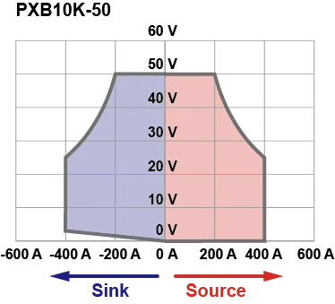
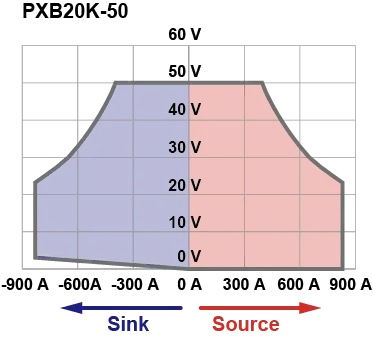
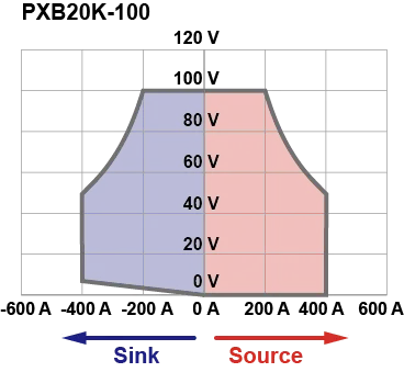
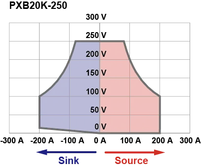
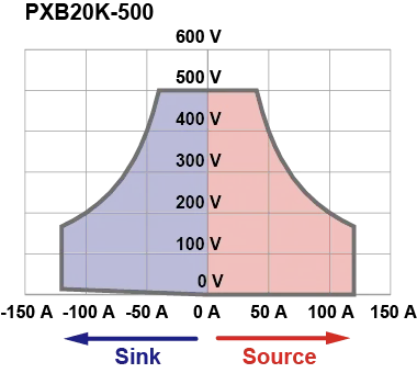
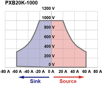
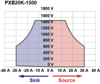
Mains-powered power supply with a wide range of operating ranges and combinations of voltage and current settings.
Source
If the voltage of the connected DUT is lower than the voltage setting of the PXB series, current flows from the PXB series to the DUT.
Sink
If the voltage of the connected DUT is higher than the voltage setting of the PXB series, current flows from the DUT to the PXB series.
Reasons the PXB Series is recommended.
Highly stable operation
with high resistance to capacitive loads
Designed for highly stable operation, without oscillation or overshoot even when a load with a large capacitive component is connected.
Slew rate and response can be varied to match the characteristics of the connected load, suppressing oscillation and overshoot.

Achieves high-speed rise and fall times
Achieves a rise/fall time of 10 ms, which is several tens of times faster than conventional switching power supplies. Enabling high-speed power fluctuation testing that cannot be handled by ordinary DC power supplies.

High power density
High-power & compact
Condenses a 20 kW large-capacity output into a 3U-size chassis.

Selectable power input
Full output at rated power regardless of input voltage
Choose from 3-phase 3-wire 200 V or 400 V models. No output limitation for either input voltage.

Reliable and solid performance
even under high temperatures
Solid performance under operating temperatures of 0°C to 50°C. Exhibits full performance even in environments with severe ambient temperatures, such as when installed in equipment. (Excluding some models.) Caution: PXB10K-50, PXB20K-50, PXB20K-100 and PXB20K-250 operates in the temperature range of 0°C to +40°C.

External control function
The EXT CONT connector on the rear panel can be used to control the PXB series with external devices. The general-purpose digital input and output terminals can be assigned any function, facilitating system construction in combination with other measurement devices.
Digital I/O standard for both NPN and PNP type PLCs. Analog I/O is isolated from output terminals as standard, allowing safe analog control from PLC.
Application 1Inverter and motor evaluation test

Application 2Aging tests for bidirectional DC/DC converters

Features
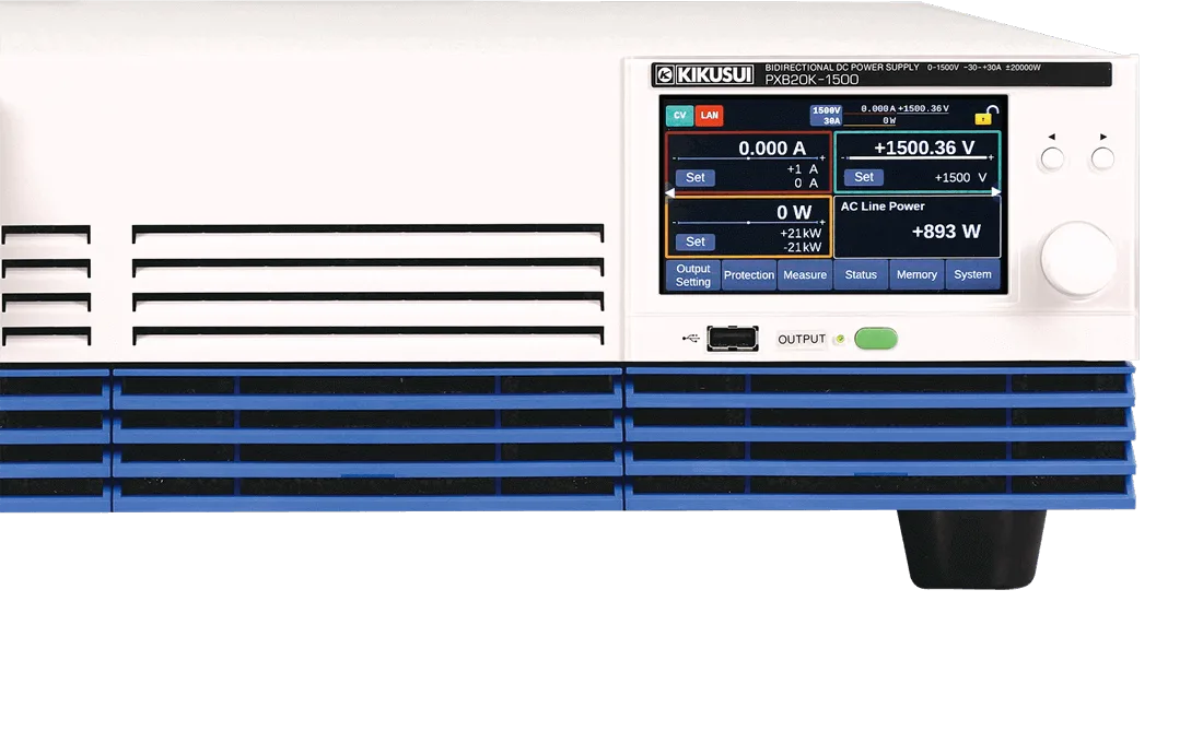
Priority operation mode
Mode of operation can be set, as constant voltage (CV), constant current (CC), or constant power (CP), when output is turned on. Overshoot can be prevented by setting CC mode priority when batteries, power supplies, etc. are connected.
SEAM mode
Equipped with SEAM mode allowing current to flow in both directions without changing voltage values. Suitable for charging and discharging storage batteries. Can suppress current overshoots and undershoots which may often occur during operation mode switching after charge/discharge.

Optimized for different purposes and applications, with selectable response speeds
Required response speed of power supply equipment varies depending on test conditions and load specifications. The PXB series can change the response speed of the power supply as desired to suit the application.
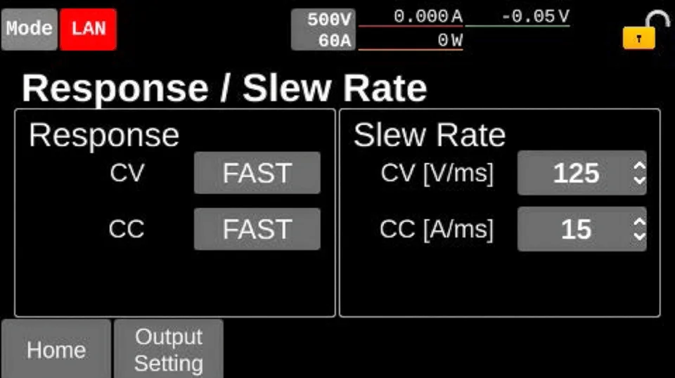
Response
FAST, SLOW
Slew rate
Selectable in 5 steps
Variable internal resistance function
Function can change the output voltage value in constant voltage operation, according to the output current value based on the set resistance value. Simple simulation of Internal resistance of rechargeable batteries and wire harnesses etc.
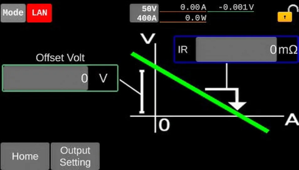
| Setting range | PXB10K-50 | 0 mΩ to 126 mΩ |
|---|---|---|
| PXB20K-50 | 0 mΩ to 63 mΩ | |
| PXB20K-100 | 0 mΩ to 315 mΩ | |
| PXB20K-250 | 0 mΩ to 1575 mΩ | |
| PXB20K-500 | 0 mΩ to 5250 mΩ | |
| PXB20K-1000 | 0 mΩ to 21000 mΩ | |
| PXB20K-1500 | 0 mΩ to 63000 mΩ |

Sequence function
Preset operations can be run continuously. Total of 30 programs, and up to 10,000 steps can be created for all programs. Programs stored in the unit’s memory, and data can be exported to a USB memory stick from the front panel.

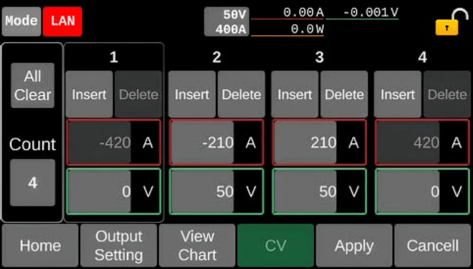
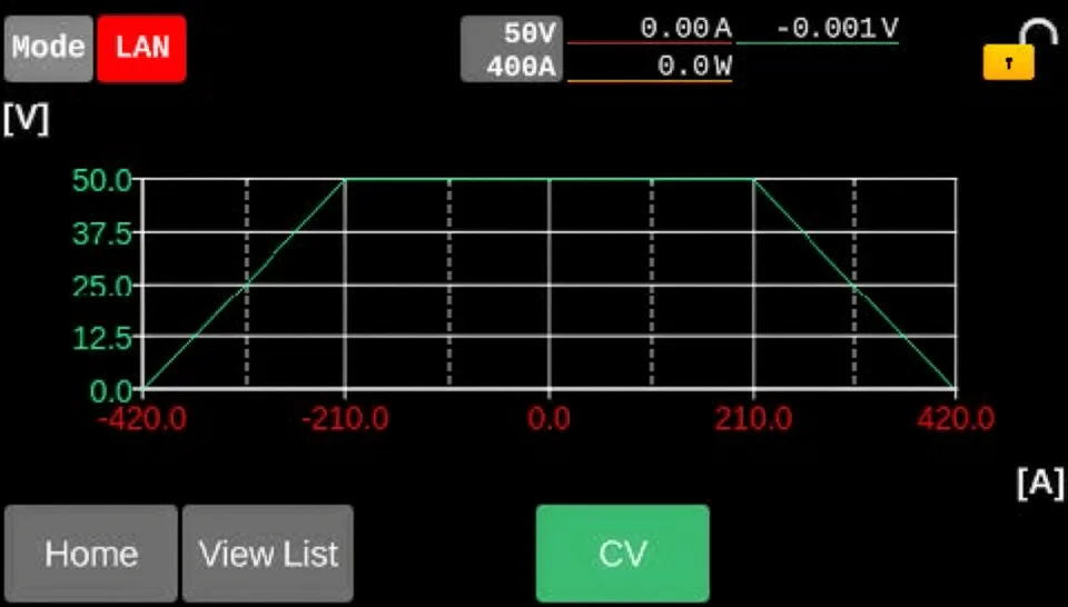
I-V characteristic function
By registering multiple arbitrary points on the I-V characteristics, arbitrary I-V characteristics can be set for each CC and CV operation mode. Arbitrary points can be registered from 3 to 100, making it possible to simulate the I-V characteristics of rechargeable batteries and other devices.


Pulse function / Sign function
“Pulse” operation can be set, which repeatedly executes a binary setting, or “sine” operation, changing the current in a sinusoidal manner.

Regenerative function (on-premises) contributes to carbon neutrality.
When power is regenerated to the main unit from an inverter or battery, the load power is converted to reusable power and regenerated to the AC LINE. This can contribute to reducing the amount of heat exhaust and saving energy.
*Regenerative efficiency of over 90% (at rated load).
*The PXB series is designed for on-site regeneration. Use in an environment where the power on-site is greater than the regenerative power.
Up to 25 units can be operated in parallel, achieving 500 kW *
Including master machine, up to 25 units (500 kW) can be operated in parallel. Connection is with one-control parallel operation, and the panel of the master machine can control and display the entire system. With the automatic recognition function, the need for complicated settings is eliminated, allowing the construction of high-capacity systems.
* Parallel operation is possible between models with different input rated voltages. Please contact us if you wish to operate more than 10 units in parallel.

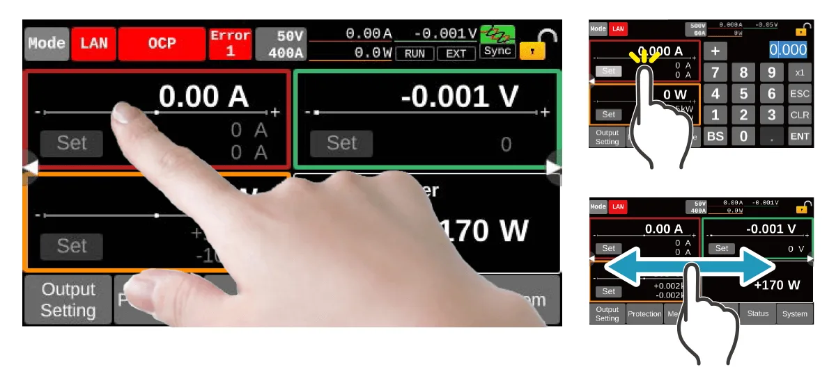
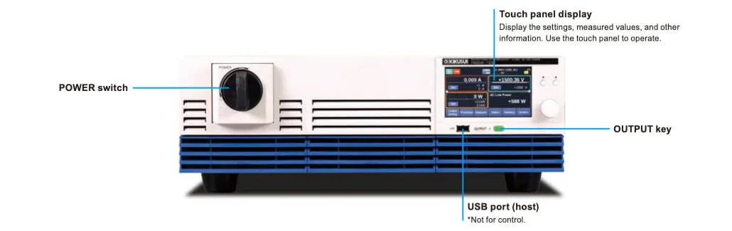
Equipped with touch panel display
By pressing or swiping a finger on the display, on-screen items can be selected, or numerical values set. The display is pressure-sensitive and can be operated even with gloves.
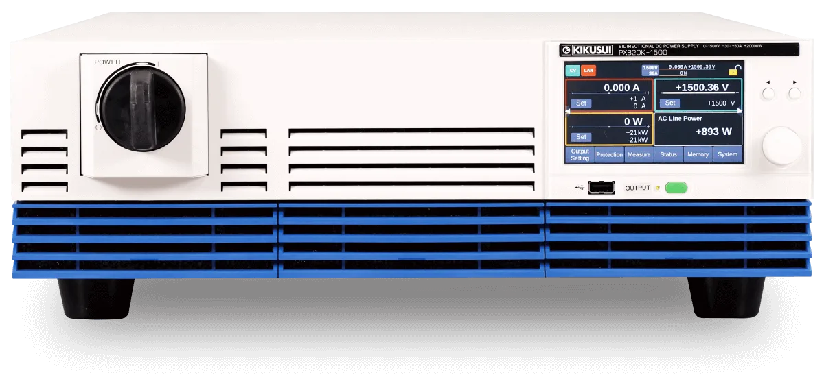
Panel explanation

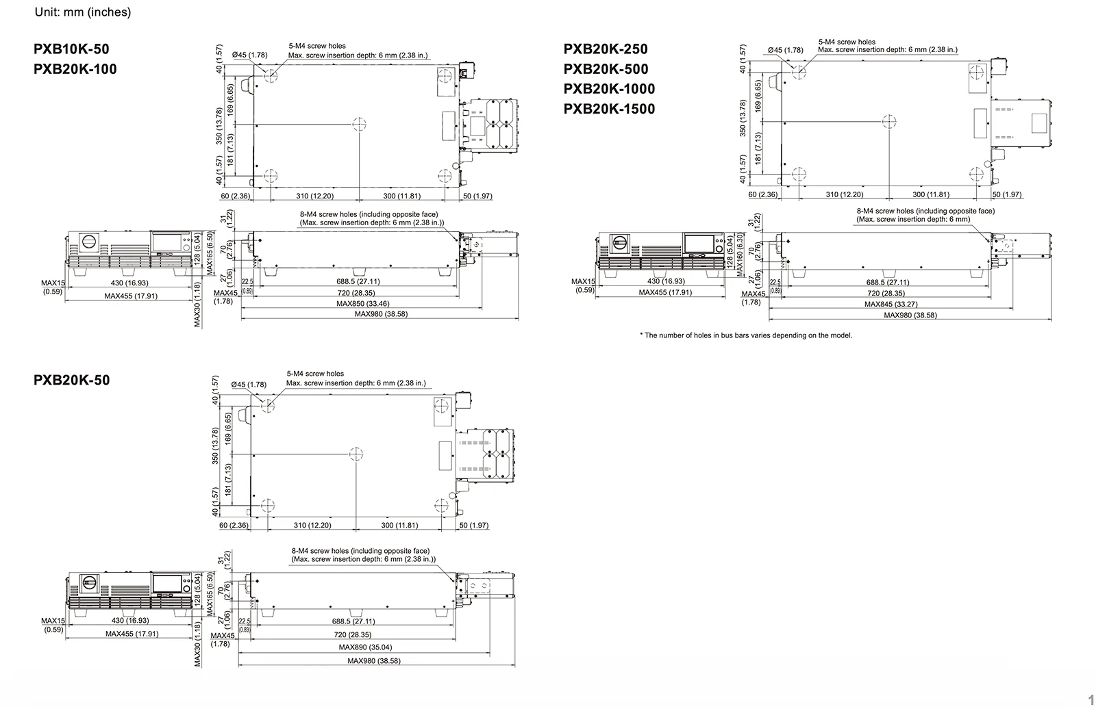
Outline drawing are common to all models. *Maximum dimensions include protrusions and accessory covers.
External Control
The EXT CONT connector on the rear panel can be used to control the PXB series with external devices. The general-purpose digital input and output terminals can be assigned any function, facilitating system construction in combination with other measurement devices.
Digital I/O standard for both NPN and PNP type PLCs. Analog I/O is isolated from output terminals as standard, allowing safe analog control from PLC.
| Method | Function |
|---|---|
| Analog input | Voltage and current value settings |
| Analog output | Monitoring of voltage and current values |
| General-purpose isolated digital input (Ch.1 to ch.5) *Photocoupler isolated input (Supports both current sink and source) |
|
| Digital input (Ch.6) | HIGH alarm generation (Fixed) |
| General-purpose isolated digital output (Ch.1 to ch.6) *Semiconductor relay output |
|
External Control Interface (EXT-CONT)
Uses the D-Sub25 pin connector on the rear panel.
| Terminal No. | Method | I/O | Name | Description |
|---|---|---|---|---|
| 1 | Digital | O | OUT Ch.1 | General-purpose output terminal |
| 2 | Digital | O | OUT Ch.2 | General-purpose output terminal |
| 3 | Digital | O | OUT Ch.3 | General-purpose output terminal |
| 4 | – | – | DO COM | Digital output common |
| 5 | – | – | DI COM | Digital input common |
| 6 | Digital | I | IN Ch.1 | General-purpose input terminal |
| 7 | Digital | I | IN Ch.2 | General-purpose input terminal |
| 8 | Digital | I | IN Ch.3 | General-purpose input terminal |
| 9 | – | O | +12V OUT | 12 V reference voltage available for digital input |
| 10 | – | – | – | Not used |
| 11 | – | – | A COM | Analog signal common |
| 12 | Analog | O | VMON | Voltage monitor |
| 13 | Analog | O | Range status output | Current monitor |
| 14 | Digital | O | OUT Ch.4 | General-purpose output terminal |
| 15 | Digital | O | OUT Ch.5 | General-purpose output terminal |
| 16 | Digital | O | OUT Ch.6 | General-purpose output terminal |
| 17 | – | – | DO COM | Digital output common |
| 18 | – | – | DI COM | Digital input common |
| 19 | Digital | I | IN Ch.4 | General-purpose input terminal |
| 20 | Digital | I | IN Ch.5 | General-purpose input terminal |
| 21 | Digital | I | H ALARM IN | HIGH alarm EXT HIGH occurrence |
| 22 | – | – | 12V COM | 12 V reference voltage common |
| 23 | – | – | A COM | Analog signal common |
| 24 | Analog | I | EXT CV | Voltage control in the constant voltage mode |
| 25 | Analog | I | EXT CC/CP | Current control in the constant current / power modes |
Specifications
Unless specified otherwise, the specifications are for the following settings and conditions.
- The product is warmed up for at least 30 minutes.
The used terminology is as follows:
- TYP: These are typical values that are representative of situations where the product operates in an environment with an ambient temperature of 23°C (73.4°F). These values do not guarantee the performance of this product.
- setting: Indicates a setting.
- reading: Indicates a readout value.
- rating: Indicates a rated value.
- Open: Indicates equivalence to the state in which the DC OUTPUT terminals are opened.
- +, −: + sign indicates source, − sign indicates sink.
- Vout: Indicates an output voltage.
Output rating
| Item | PXB10K-50 | PXB20K-50 | PXB20K-100 | PXB20K-250 | PXB20K-500 | PXB20K-1000 | PXB20K-1500 |
|---|---|---|---|---|---|---|---|
| Rated power | ±10,000 W | ±20000 W | ±20000 W | ±20000 W | ±20000 W | ±20000 W | ±20000 W |
| Rated voltage (source) *1 | 0 V to 50 V | 0 V to 50 V | 0 V to 100 V | 0 V to 250 V | 0 V to 500 V | 0 V to 1000 V | 0 V to 1500 V |
| Operating voltage (sink) *2 | 3 V to 50 V | 3 V to 50 V | 7 V to 100 V | 15 V to 250 V | 10 V to 500 V | 20 V to 1000 V | 30 V to 1500 V |
| Rated current *1 | ±400 A | ±800 A | ±400 A | ±200 A | ±120 A | ±60 A | ±30 A |
*1. Limited by the maximum output power. *2. Operating voltage at which the rated sink current can be applied.
Output voltage
| Item | PXB10K-50 | PXB20K-50 | PXB20K-100 | PXB20K-250 | PXB20K-500 | PXB20K-1000 | PXB20K-1500 | ||
|---|---|---|---|---|---|---|---|---|---|
| Maximum settable voltage | 52.5 V | 52.5 V | 105 V | 262.5 V | 525 V | 1050 V | 1575 V | ||
| Setting accuracy | ±(0.2 % of setting + 0.1 % of rating) | ||||||||
| Resolution | 0.005 V | 0.005 V | 0.001 V | 0.02 V | 0.05 V | 0.1 V | 0.1 V | ||
| Power fluctuation*1 | ±10 mV | ±10 mV | ±20 mV | ±50 mV | ±100 mV | ±200 mV | ±300 mV | ||
| Load variation*2 | ±40 mV | ±40 mV | ±50 mV | ±125 mV | ±250 mV | ±500 mV | ±750 mV | ||
| Remote sensing Maximum compensation voltage (reciprocating) | 10 % of rating | ||||||||
| Internal resistance setting upper limit | 126 mΩ | 63 mΩ | 315 mΩ | 1575 mΩ | 5250 mΩ | 21000 mΩ | 63000 mΩ | ||
| Internal resistance setting resolution | 1 mΩ | 1 mΩ | 1 mΩ | 1 mΩ | 1 mΩ | 2 mΩ | 5 mΩ | ||
| Response switching | FAST, SLOW | ||||||||
| Slew rate switching (TYP) | 12.5 V/ms or more *3 | 12.5 V/ms or more *3 | 25 V/ms or more*3 | 62.5 V/ms or more *3 | 125 V/ms or more *3 | 250 V/ms or more *3 | 375 V/ms or more *3 | ||
| 12.5 V/ms | 12.5 V/ms | 25 V/ms | 62.5 V/ms | 125 V/ms | 250 V/ms | 375 V/ms | |||
| 1.25 V/ms | 1.25 V/ms | 2.5 V/ms | 6.25 V/ms | 12.5 V/ms | 25.0 V/ms | 37.5 V/ms | |||
| 0.125 V/ms | 0.125 V/ms | 0.25 V/ms | 0.625 V/ms | 1.25 V/ms | 2.50 V/ms | 3.75 V/ms | |||
| 0.0125 V/ms | 0.0125 V/ms | 0.025 V/ms | 0.0625 V/ms | 0.125 V/ms | 0.250 V/ms | 0.375 V/ms | |||
| Source only *4 | Transient response *5 | 8 ms or less | 8 ms or less | 8 ms or less | 8 ms or less | 8 ms or less | 10 ms 以下 | 10 ms 以下 | |
| Ripple noise *6 | p-p*7 | 250 mV | 250 mV | 300 mV | 375 mV | 1000 mV | 1500 mV | 2500 mV | |
| rms*8 | 37 mV | 30 mV | 75 mV | 125 mV | 250 mV | 500 mV | 750 mV | ||
| Rise time *9 | Full load *10 | 10 ms | |||||||
| No load | 10 ms | ||||||||
| Fall time *11 | Full load *10 | 10 ms | |||||||
| No load | 10 ms | ||||||||
*1. 180 Vac to 252 Vac for 200 Vac input, 342 Vac to 504 Vac for 400 Vac input. At the constant load. *2. The amount of change that occurs when the load is changed from no load to full load (rated output power/rated output voltage) with rated output voltage. The value is measured at the sensing point. *3. MAX will appear on the display. *4. In the case that the CV mode response setting is set to FAST. *5. The amount of time required for the output voltage to return to a value within “rated output voltage ±(0.1 % + 10 mV).” The load current fluctuation is 50 % to 100 % of the maximum current with the set output voltage. *6. At the rated output current. Values measured using JEITA RC-9131C probe and 100:1 probe. *7. Measurement frequency band: 10 Hz to 20 MHz *8. Measurement frequency band: 10 Hz to 1 MHz *9. 10 % to 90 % of the rated output voltage. *10.For a pure resistance. *11. 90 % to 10 % of the rated output voltage.
Output current
| Item | PXB10K-50 | PXB20K-50 | PXB20K-100 | PXB20K-250 | PXB20K-500 | PXB20K-1000 | PXB20K-1500 |
|---|---|---|---|---|---|---|---|
| Settable maximum source current *1 | +420 A | +840 A | +420 A | +210 A | +126 A | +63 A | +31.5 A |
| Settable maximum sink current *1 | -420 A | -840 A | -420 A | -210 A | -126 A | -63 A | -31.5 A |
| Seamless setting current range *1 | -420 A to +420 A | -840 A to +840 A | -420 A to +420 A | -210 A to +210 A | -126 A to +126 A | -63 A to +63 A | -31.5 A to +31.5 A |
| Setting accuracy | ±(0.75 % of rating) | ||||||
| Resolution | 0.05 A | 0.1 A | 0.05 A | 0.02 A | 0.01 A | 0.005 A | 0.002 A |
| Line regulation | ±800 mA | ±1600 mA | ±800 mA | ±400 mA | ±240 mA | ±120 mA | ±60 mA |
| Load regulation | ±800 mA | ±1600 mA | ±800 mA | ±400 mA | ±240 mA | ±120 mA | ±60 mA |
| Rise time (Short-circuit) (TYP) *2 | 5 ms | ||||||
| Fall time (Short-circuit) (TYP) *3 | 5 ms | ||||||
| Charge/discharge switching time (TYP) | 10 ms | ||||||
| Response switching | FAST, SLOW | ||||||
| Slew rate switching (TYP) *4 | 100 A/ms or more*3 | 200 A/ms or more *3 | 100 A/ms or more*3 | 50 A/ms or more *3 | 30 A/ms or more *3 | 15 A/ms or more *3 | 7.5 A/ms or more *3 |
| 100 A/ms | 200 A/ms | 100 A/ms | 50 A/ms | 30 A/ms | 15 A/ms | 7.5 A/ms | |
| 10 A/ms | 20 A/ms | 10 A/ms | 5 A/ms | 3 A/ms | 1.5 A/ms | 0.75 A/ms | |
| 1 A/ms | 2 A/ms | 1.0 A/ms | 0.5 A/ms | 0.3 A/ms | 0.15 A/ms | 0.075 A/ms | |
| 0.1 A/ms | 0.2 A/ms | 0.10 A/ms | 0.05 A/ms | 0.03 A/ms | 0.015 A/ms | 0.0075 A/ms | |
*1. During parallel operation, this will be the value multiplied by the number of units in the configuration. *2. In the case that the CC mode response setting is set to FAST: Applied in response to changes from 10 % to 90 % of rated output current. *3. In the case that the CC mode response setting is set to FAST: Applied in response to changes from 90 % to 10 % of rated output current. *4. MAX will appear on the display.
Output power
| Item | 10 kW models | 20 kW models |
|---|---|---|
| Settable maximum source power *1 | +10500 W | +21000 W |
| Settable maximum sink power *1 | -10500 W | -21000 W |
| Seamless setting power range *1 | -10500 W〜+10500 W | -21000 W to +21000 W |
| Setting accuracy *2 | ±(0.5 % of power rating + 0.5 % of current rating × Vout) | |
| Resolution | 1 W | 2 W |
*1 During parallel operation, this will be the value multiplied by the number of units in the configuration. *2 Equal to or higher than 5 % of the rated power is guaranteed. Less than 5 % of the rated power is guaranteed as a TYP value.
200 V three-phase three-wire input
| Item | 10 kW models | 20 kW models |
|---|---|---|
| Rated input rating | 200 Vac to 240 Vac, 50 Hz to 60 Hz | |
| Input voltage range | 180 Vac to 252 Vac | |
| Input frequency range | 47 Hz to 63 Hz | |
| Input current (MAX) *1 | 40 A (180 V) | 80 A (180 V) |
| Input power (MAX) *1 | 12 kVA | 24 kVA |
| Inrush current (TYP)*2 | 90 A | |
| Power factor (TYP)*1 | 0.96 | |
| Output hold time | 10 ms or more | |
*1 At the rated output power for the rated output current. *2 Maximum peak current value when the POWER switch is turned on. (Excluding the surge current to the input filter capacitor.)
400 V three-phase three-wire input
| Item | 10 kW models | 20 kW models |
|---|---|---|
| Rated input rating | 380 Vac to 480 Vac, 50 Hz to 60 Hz | |
| Input voltage range | 342 Vac to 504 Vac | |
| Input frequency range | 47 Hz to 63 Hz | |
| Input current (MAX) *1 | 20 A (342 V) | 40 A (342 V) |
| Input power (MAX) *1 | 12 kVA | 24 kVA |
| Inrush current (TYP)*2 | 70 A | |
| Power factor (TYP)*1 | 0.96 | |
| Output hold time | 10 ms or more | |
*1. At the rated output power for the rated output current. *2. Maximum peak current value when the POWER switch is turned on. (Excluding the surge current to the input filter capacitor.)
Display
| Item | PXB10K-50 | PXB20K-50 | PXB20K-100 | PXB20K-250 | PXB20K-500 | PXB20K-1000 | PXB20K-1500 | |
|---|---|---|---|---|---|---|---|---|
| Voltmeter | Maximum display | ±60.000 V | ±60.000 V | ±120.00 V | ±300.00 V | ±600.00 V | ±1200.00 V | ±1800.00 V |
| Display accuracy | ±(0.1 % of reading + 0.2 % of rating) | |||||||
| Ammeter | Maximum display | ±560.00 A | ±1120.00 A | ±560.0 A | ±1120.0 A | ±168.00 A | ±84.000 A | ±42.000 A |
| Display accuracy | ±(0.75 % of rating) | |||||||
| Wattmeter | Maximum display*1 | ±12.000 kW | ±24.000 kW | |||||
| Display accuracy | Display the integrated value of voltmeter and ammeter | |||||||
| Operation display | Output On/Off, Operation Mode (CV/CC/CP), Remote (LAN), Alarm, SCPI Error, Power Off, Key Lock, Remote Sensing, Parallel Operation, External Control | |||||||
*1 The unit will be W if it is less than 10 kW.
External analog I/O
| Item | Common to all models | ||
|---|---|---|---|
| Input | Input points | 2 points | |
| Voltage (CV) control | Setting range | 0 % to 100 % of the rated output voltage | |
| Input voltage range | 0 V to +5 V or 0 V to +10 V (Selectable) | ||
| Accuracy | ±(1 % of rating) | ||
| Current (CC) control Power (CP) control *1 | Setting range | −100 % to +100 % of the rated current and rated power | |
| Input voltage range | −5 V to +5 V or −10 V to +10 V (Selectable) | ||
| Accuracy | ±(1 % of rating) | ||
| Output | Output points | 2 points | |
| Voltage monitor (VMON) | Monitor range | 0 % to 100 % of the rated output voltage | |
| Output voltage range | 0 V to +5 V or 0 V to +10 V (Selectable) | ||
| Accuracy | 1 % of rating | ||
| Current monitor (IMON) | Monitor range | −100 % to +100 % of the rated output voltage | |
| Output voltage range | −5 V to +5 V or −10 V to +10 V (Selectable) | ||
| Accuracy | ±(1 % of rating) | ||
*1 Select either current control or power control.
External digital input
| Item | Common to all models | |
|---|---|---|
| Fixed input points | 1 point (Polarity switchable) | |
| Selected input points | 5 points (Polarity switchable) | |
| Input form | Photocoupler isolated input (Applicable to both current sink / source output) | |
| Fixed function | ALARM IN | HIGH alarm occurrence |
| Selecting function | OFF | Do not use terminals |
| OUTPUT ON | Turn on the output | |
| OUTPUT OFF | Turn off the output | |
| OUTPUT CTRL | Turn on of off the output | |
| L ALARM IN | LOW alarm occurrence | |
| ALARM CLR | LOW alarm clearance | |
| SEQ RUN | Sequence start/end | |
| SEQ PAUSE | Sequence pause/resume | |
| INTEG CTRL | Starting/stopping integration measurement | |
| INTEG RESET | Resetting integration measurement data | |
| ACQUIRE TRIG | Input the measurement trigger | |
| SEQ TRIG IN | Input the trigger for sequence | |
| MEM1 RECALL | Recall preset memory 1 | |
| MEM2 RECALL | Recall preset memory 2 | |
| External circuit power supply range | 12 V to 24 Vdc (±10 %) | |
External digital output
| Item | Common to all models | |
|---|---|---|
| Output points | 6 points (Polarity switchable) | |
| Output form | Semiconductor relay output | |
| Selecting function | OFF | Do not use terminals |
| OUTPUT ON | Outputting the signal while the output is ON | |
| POWER ON | Signal is output when power supply is on and output is possible | |
| H ALARM OUT | Output a signal when a HIGH alarm occurs | |
| L ALARM OUT | Output a signal when a LOW alarm occurs | |
| CC STATUS | Output a signal when operating in the CC mode | |
| CV STATUS | Output a signal when operating in the CV mode | |
| SEQ TRIG OUT | Output the trigger for sequence | |
| SEQ STATUS | Signal is output while the sequence is running | |
| EXT DIN BUSY | Output a signal when the digital input is in BUSY status | |
| MEM1 ACT TIME | Signal is output when the setting is completed for preset memory 1 | |
| MEM2 ACT TIME | Signal is output when the setting is completed for preset memory 2 | |
| RELAY DRIVE | Output a signal after approx. 100 ms in step with on/off of the DC OUTPUT terminal output. You can set this parameter to only Ch.6. | |
Communication interface
| Item | Common to all models | |
|---|---|---|
| Common specifications | Software protocol | IEEE std. 488.2-1992 |
| Command language | Complies with SCPI Specification 1999.0 | |
| RS232C | Hardware | D-SUB 9-pin connector Baud rate: 1200, 2400, 4800, 9600, 19200, 38400, 57600, 115200 bps Data length: 8 bits, Stop bits: 1 bit, Parity bit: None Flow control: No, CTS-RTS |
| Program message terminator | LF during reception, LF during transmission. | |
| USB (device) | Hardware | Standard type B socket. Complies with the USB 2.0 specifications; data rate: 480 Mbps (high speed) |
| Program message terminator | LF or EOM during reception, LF + EOM during transmission | |
| Device class | Complies with the USBTMC-USB488 device class specifications | |
| USB (host) | Hardware | Standard type A socket. Complies with the USB 2.0 specifications; data rate: 480 Mbps (high speed) |
| LAN | Hardware | IEEE 802.3 100BASE-TX or 10BASE-T Ethernet |
| Communication protocol | SCPI-RAW, SCPI-Telnet, HiSLIP, VXI-11 | |
| Program message terminator | SCPI-RAW: LF during reception, LF during transmission HiSLIP: LF or END during reception, LF + END during transmission. | |
| Compliant standards | LXI Version 1.5 Specifications 2016 | |
Others
| Item | Common to all models | ||
|---|---|---|---|
| Synchronization function (clock synchronization) | Overview | SYNC icon is displayed on the display when synchronization is established with the internal clock after connecting with other PXB series using the EXT SYNC connector. | |
| Sequence synchronization | Synchronization of the program start and step start. | ||
| Measurement synchronization | Synchronization of the measurement start | ||
| Output synchronization | Synchronization of output ON/OFF | ||
| Sequence function | Operation mode | CV, CC, and CP modes | |
| Maximum number of programs | 30 | ||
| Maximum number of steps | 10000 | ||
| Step execution time | 1 ms to 3600 000 s | ||
| Loop count | 1 to 100000, or infinite | ||
| Sine Function | Operation mode | CV/CC mode | |
| Frequency setting range | 1 Hz to 1000 Hz | ||
| Frequency resolution | 1 Hz to 10 Hz | 0.2 Hz | |
| 12 Hz to 100 Hz | 2 Hz | ||
| 120 Hz to 1000 Hz | 20 Hz | ||
| CV | Maximum setting | Setting range up to 105 % of rated voltage | |
| Maximum offset setting | Setting range up to 105 % of rated voltage | ||
| CC | Maximum setting | Setting range up to 210 % of rated current | |
| Maximum offset setting | Setting range up to ±105 % of rated current | ||
| Pulse function | Operation mode | CV/CC mode | |
| Frequency setting range | 1 Hz to 1000 Hz | ||
| Frequency resolution | 1 Hz to 10 Hz | 0.01 Hz | |
| 12 Hz to 100 Hz | 0.1 Hz | ||
| 120 Hz to 1000 Hz | 1 Hz | ||
| CV | High level rated current | Setting range up to 105 % of rated voltage | |
| Low level rated current | Setting range up to 105 % of rated voltage | ||
| CC | High level rated current | Setting range up to 105 % of rated current | |
| Low level rated current | Setting range up to 105 % of rated current | ||
| Duty cycle | 2.5 % to 97.5 % | ||
| Measurement trigger | Measurement start condition (trigger source) | Conditions for starting measurement can be selected (when inputting from display, when inputting commands by remote control, when inputting signals by external control, and when operating in synchronization) | |
| Number of measurements | 1 to 65536 | ||
| Measurement delay time | Setting range | 0 s to 100 s | |
| Resolution | 0.1 ms | ||
| Measurement interval | Setting range | 0.1 ms to 3600 s | |
| Resolution | 0.1 ms | ||
| Measurement time | Setting range | 0.1 ms to 1 s | |
| Resolution | 0.1 ms | ||
| I-V characteristic function | Operation mode | CV/CC mode | |
| Number of setup items | 3 to 100 items (interpolated between points with straight lines) | ||
| Preset memory | Number of memory entries | 20 | |
| Saved setting | Values in CV, CC, and CP modes, protection function values, and IR values | ||
| Setup Memory | Number of memory entries | 21 | |
| Saved setting | On/off of the output from the DC OUTPUT terminal, Output voltage value/Output current value/Output power value, Output current for seamless operation (DC SEAM), Output mode, Response, Slew Rate, Priority operation mode (Priority when output is ON), Impedance Setting When the Output is Off (Impedance when output is OFF), Value of the pulse function (Duty, Frequency, High, Low), Value of the sine function (Amplitude, Frequency, Offset), Number of I-V characteristics (Count), Internal resistance value (IR), Over voltage protection (OVP), Under voltage protection (UVP, UVP Enable), Over current protection (OCP(+), OCP(-), Delay), Over power protection (OPP(+), OPP(-)), Line overvoltage protection (Line OVP), Measurement trigger settings (Source, Count, Delay, Enable, Timer), Integration settings (Gate, Reset) | ||
| key lock | Level 1 | Output on/off and preset memory recall are available | |
| Level 2 | Output on/off are available | ||
| Level 3 | Output off is available | ||
| Number of parallel operated load modules | Up to 25 units | ||
Protection functions
| Item | Common to all models | |
|---|---|---|
| LOW Alarm | All 6 types |
OVP (overvoltage protection) / OCP (overcurrent protection) / OPP (overpower protection) / UVP (undervoltage protection) / Watchdog Alarm (communication abnormality protection) / External Alarm LOW Level (external input alarm detection) |
| HIGH Alarm | All 13 types |
Reverse Alarm (Reverse-connection detection protection) / Overheat protection / Line OVP (Grid overvoltage protection) / Line UVP (Grid undervoltage protection) / Line Frequency Error (Grid frequency abnormality protection), etc. |
General specifications
| Item | PXB10K-50 | PXB20K-50 | PXB20K-100 | PXB20K-250 | PXB20K-500 | PXB20K-1000 | PXB20K-1500 | |
|---|---|---|---|---|---|---|---|---|
| Weight | Approx. 28 kg (61.73 lbs) | Approx. 41 kg (90.39 lbs) | Approx. 40 kg (88.18 lbs) | Approx. 39 kg(85.98 lbs) | Approx. 38 kg (83.78 lbs) | Approx. 37 kg (81.57 lbs) | Approx. 37 kg (81.57 lbs) | |
| Dimensions | Refer to Outline Drawing | |||||||
| Environmental conditions | Operating environment | Indoor use, overvoltage category II | ||||||
| Operating temperature | 0 °C to +40 °C (32 °F to +104 °F) | 0 °C to +50 °C (32 °F to +122 °F) | ||||||
| Operating humidity | 20 % rh to 85% rh (no condensation) | |||||||
| Storage temperature | −25°C to +60°C (−13 °F to +140 °F) | |||||||
| Storage humidity | 90 % rh or less (no condensation) | |||||||
| Altitude | Up to 2000m | |||||||
| Cooling method | Forced air cooling using fan | |||||||
| Accessories | Input terminal cover, External control connector kit (1 set), Chassis connection wire,OUTPUT terminal cover, DC OUTPUT terminal screws (1 pair), EXT SYNC connector cover, SENSING connector cover,SENSING connector (2 pc.), Synchronized operation signal cable kit, Safety Information (1 copy), China RoHS sheet (1 sheet),Getting Started Guide (1 copy), Heavy object warning label (1 pc.) | |||||||
| Withstanding voltage | Between input and GND | 2200 Vac for 1 minute | ||||||
| Between input and output | ||||||||
| Between output and GND | 500 Vdc for 1 minute | 500 Vdc for 1 minute | 500 Vdc for 1 minute | 1000 Vdc for 1 minute | 1800 Vdc for 1 minute | 1800 Vdc for 1 minute | 3000 Vdc for 1 minute | |
| Insulation resistance | Between input and GND | 30 MΩ, 500 Vdc | ||||||
| Between input and output | 30 MΩ, 500 Vdc | 30 MΩ, 500 Vdc | 30 MΩ, 500 Vdc | 30 MΩ, 600 Vdc | 30 MΩ, 1000 Vdc | |||
| Isolation voltage | ±250 V | ±250 V | ±250 V | ±600 V | ±1000 V | ±1000 V | +2000 V/−1000 V | |
| Electromagnetic compatibility (EMC)*1*2 | Complies with the requirements of the following directive and standards. EMC Directive 2014/30/EU EN 61326-1 (Class A*3) | |||||||
| Safety*1 | Complies with the requirements of the following directive and standards. Low Voltage Directive 2014/35/EU*2 EN 61010-1 (Class I*4, Overvoltage category II, Pollution Degree 2*5) UL 61010-1*6 CAN/CSA -C 22.2 NO.61010-1*6 | |||||||
*2. Only for models with CE mark/UKCA mark on their body.
*3. This is a Class A instrument. This product is intended for use in an industrial environment. This product may cause interference if used in residential areas. Such use must be avoided
unless the user takes special measures to reduce electromagnetic emissions to prevent interference to the reception of radio and television broadcasts.
*4. This is a Class I instrument. Be sure to ground this product’s protective conductor terminal. The safety of this product is guaranteed only when the product is properly grounded.
*5. Pollution is addition of foreign matter (solid, liquid or gaseous) that may produce a reduction of dielectric strength or surface resistivity. Pollution Degree 2 assumes that only non-conductive
pollution will occur except for an occasional temporary conductivity caused by condensation.
*6. Only on models that have cTUVus marking on the panel.
Line-up