Executive Summary
- IEC 61000-4-13 (Edition 1.2, 2015 — Edition 1.0, 2002, as amended by A1:2009 and A2:2015) verifies that equipment keeps working when its AC supply is deliberately distorted with individual harmonics, interharmonics, swept frequency components, characteristic composite waveforms (“flat curve” and “over-swing”), and mains-signalling tones. It applies to equipment rated up to 16 A per phase, with disturbance frequencies up to 2 kHz on 50 Hz systems and 2.4 kHz on 60 Hz systems. Equipment on 16⅔ Hz and 400 Hz networks is excluded.
- Test severities are set by environment class — Class 1 (protected), Class 2 (public network / commercial), Class 3 (harsh industrial) — with harmonic levels defined order by order (e.g., 5th harmonic at 4.5 % / 9 % / 12 % of U₁ for Classes 1/2/3) and interharmonic levels defined band by band up to 2/2.4 kHz. Harmonic components of 3 % and above (orders up to the 9th) are applied at both 0° and 180° phase relative to the fundamental.
- The Kikusui PCR-WEA/WEA2 Series synthesizes these waveforms directly (PWM inverter, 1 Hz–5 kHz, intrinsic THD as low as 0.3 %), and Kikusui’s published support matrix lists the SD009-PCR-LE/WE “Quick Immunity Sequencer 2” (QIS2) software as fully supporting every IEC 61000-4-13 test type — flat curve, over-swing, sweep in frequency, odd/even harmonics, interharmonics, and Meister curve — in both single-phase and three-phase configurations.
What Is IEC 61000-4-13?
IEC 61000-4-13, “Testing and measurement techniques — Harmonics and interharmonics including mains signalling at a.c. power port, low frequency immunity tests,” defines test methods for verifying the functional immunity of equipment (rated input current up to 16 A per phase) to harmonic and interharmonic voltage distortion and to mains-signalling frequencies on 50/60 Hz low-voltage networks.
Real mains voltage is never a clean sine. Massed rectifier loads flatten the peaks; resonances between network inductance and power-factor-correction capacitors amplify particular orders; variable-speed drives and cycloconverters inject components between integer harmonic orders; and utilities deliberately superimpose ripple-control signalling tones. Equipment whose timing, measurement, PFC, or protection circuits implicitly assume a clean sine can misbehave on such networks. IEC 61000-4-13 makes that failure mode testable by distorting the supply on purpose, in controlled, reproducible ways.
Two boundary conditions keep the scope tight: the RMS of the resultant distorted waveform is held at the nominal voltage (so the test isolates waveshape effects from level effects), and long-term thermal effects beyond 15 minutes are excluded — this is a functional immunity test, not a heating test.
Test Levels by Class
Classes follow the electromagnetic environment of IEC 61000-2-4: Class 1 — protected supplies (compatibility levels below public-network levels); Class 2 — points of common coupling with the public network and commercial/light-industrial environments; Class 3 — in-plant industrial points with heavy distorting loads; Class X — set by product committees (not below Class 2 for equipment on public supplies). Representative levels from the standard’s tables:
Individual Harmonics (% of U₁)
| Harmonic group | Class 1 | Class 2 | Class 3 |
|---|---|---|---|
| Odd, non-multiple of 3 (Table 1) — e.g., 5th / 7th | 4.5 % (5th–7th), tapering to 1.5 % (25th–37th) | 9 % (5th), tapering to 1.5 % (25th–37th) | 12 % (5th), tapering to 3 % (31st–37th) |
| Odd, multiple of 3 (Table 2) — 3rd, 9th… | 3rd: 4.5 %, 9th: 2 % (only these tested) | 3rd: 8 %, 9th: 2.5 % | 3rd–39th tested, 9 % down to 2 % |
| Even (Table 3) — 2nd, 4th… | 2nd: 3 %, 4th: 1.5 % (only these tested) | 2nd: 3 %, 4th: 1.5 % | Extended set through the 40th order, 5 % down to 1.5 % |
Phase of application: harmonic components at 3 % of U₁ and above, up to the 9th order, are applied twice — at 0° and at 180° relative to the positive zero-crossing of the fundamental. Components below 3 % are applied without a phase-shift repetition.
Interharmonics (Tables 4a/4b, % of U₁)
| Frequency band | Class 1 | Class 2 | Class 3 |
|---|---|---|---|
| 50 Hz systems: 16–100 Hz | — | 2.5 % | 4 % |
| 100–500 Hz | — | 5 % | 9 % |
| 500–750 Hz | — | 3.5 % | 5 % |
| 750–1,000 Hz | — | 2 % | 3 % |
| 1,000–2,000 Hz | — | 1.5 % | 2 % |
| 60 Hz systems: 20–120 Hz | — | 2.5 % | 4 % |
| 120–600 Hz | — | 5 % | 7.5 % |
| 600–900 Hz | — | 3.5 % | 5 % |
| 900–1,200 Hz | — | 2 % | 3 % |
| 1,200–2,400 Hz | — | 1.5 % | 2 % |
(Class 1 interharmonic testing is defined case-by-case; the dashes indicate levels not fixed in the general tables. Consult the standard for the definitive per-class tables.)
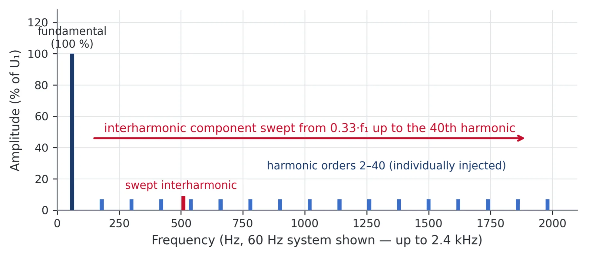
Figure 1. The spectral view: harmonic orders 2–40 are injected individually at class-dependent levels, and an interharmonic component is swept across the band up to the 40th harmonic (2 kHz on 50 Hz systems, 2.4 kHz on 60 Hz systems), dwelling to expose resonances.
The Composite and Sweep Tests
Flat Curve (Table 7)
The standard defines the flat-curve waveshape precisely: each half-wave consists of three parts — a pure sine rise from zero to a specified clip value, a constant-voltage flat top, and a pure sine fall back to zero — with the resultant RMS held at nominal. It reproduces the flattened peaks of networks dominated by rectifier loads, and stresses peak-detecting circuits, DC bus charging, and zero-crossing/timing circuits. The clip level is class-dependent (Table 7 of the standard).
Over-Swing (Table 8)
The over-swing waveshape superimposes discrete 3rd and 5th harmonic components on the fundamental with a specified phase relationship, producing peak amplification rather than flattening — representative of three-phase industrial environments and capacitor-switching/resonance effects. Levels and phases are class-dependent (Table 8).
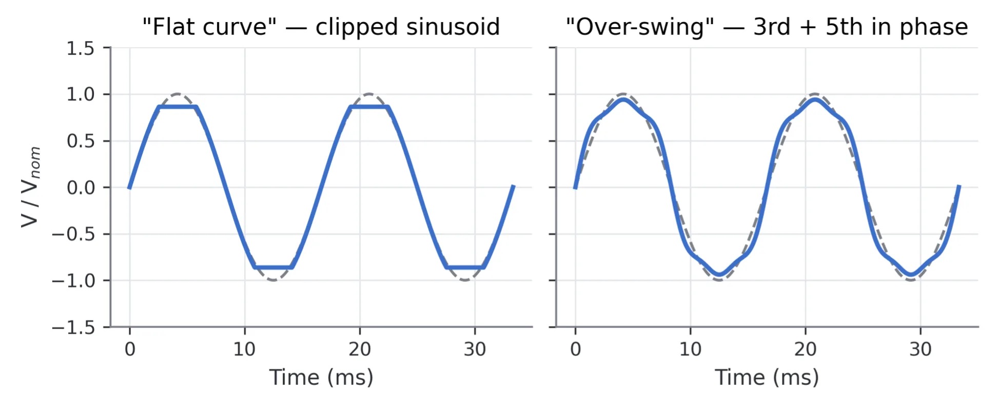
Figure 2. The two characteristic composite waveforms: the flat curve (sine rise — constant top — sine fall, RMS held at nominal) and the over-swing waveform (3rd + 5th harmonics phased for peak amplification). Dashed: ideal sine.
Sweep in Frequency (Table 9)
A single component of class-dependent magnitude is swept (continuously, or in discrete steps with a defined step size and dwell) across the band from 0.33·f₁ up to the 40th harmonic. The sweep is quasi-stationary and deliberately slow — its purpose is to find resonances: frequencies at which the EUT current or behavior shows anomalies are recorded, and the EUT is then retested at those frequencies at the harmonic-table levels. This is why complete -4-13 campaigns are long, and why automation matters.
Meister Curve (Table 11, Mains Signalling)
Utilities superimpose ripple-control signalling tones on the network. The frequency band and the compatibility level for these tones are defined not here but in IEC 61000-2-2, the environment standard: it places ripple-control systems between 110 Hz and 3 kHz (newer installations typically 110 Hz to 500 Hz) and plots the corresponding compatibility level in its Figure 3 — the curve generally known as the Meister curve. IEC 61000-4-13 applies that curve as an immunity test, as a Class 2 test, but only within its own frequency scope: signalling frequencies above the 2 kHz (50 Hz) / 2.4 kHz (60 Hz) limit of this standard exist on real networks yet fall outside the test. Levels are in the low-percent region of U₁, decreasing with frequency.
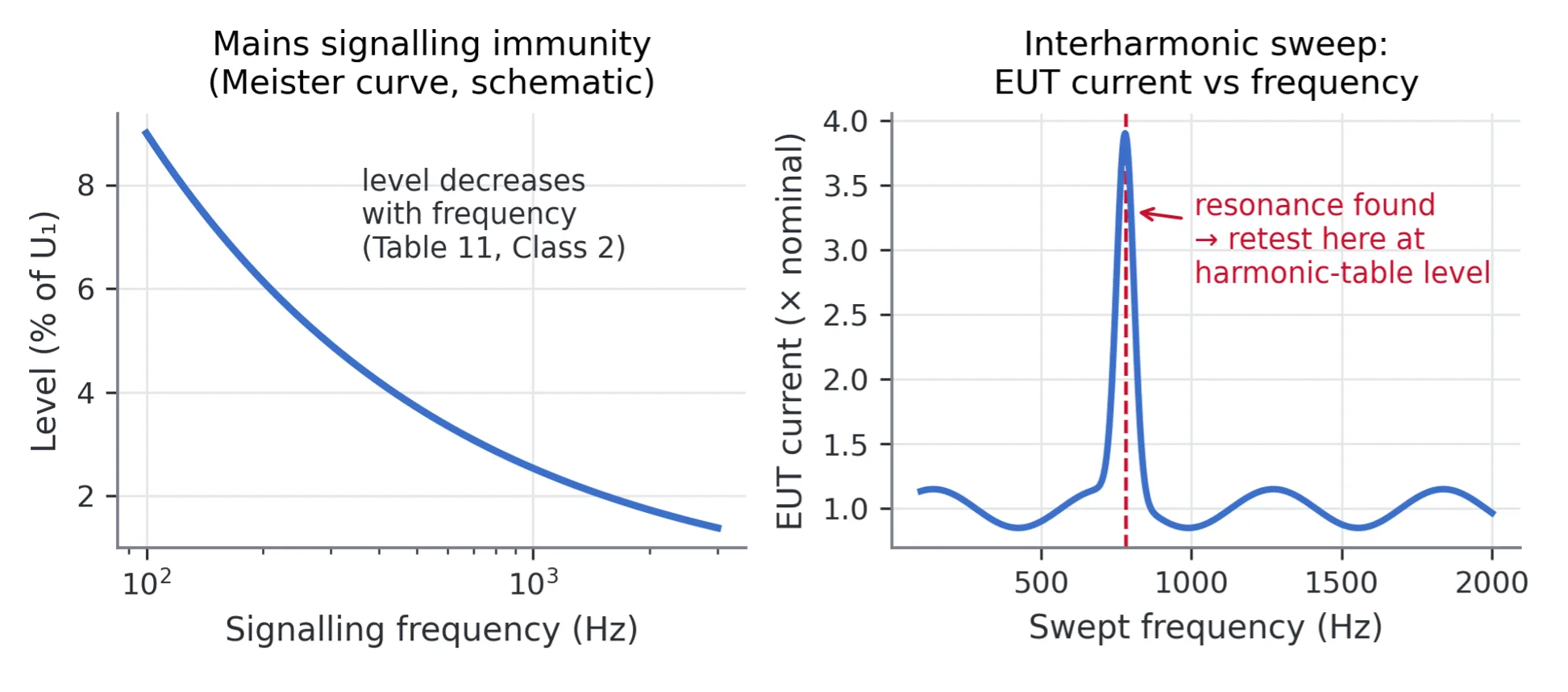
Figure 3. Left: the mains-signalling immunity level decreases with frequency (Meister curve, schematic — see Table 11 for values). Right: the purpose of the sweep — EUT current monitored across the swept band reveals a resonance, which is then retested at the harmonic-table level. Skipping the retest is a common test-plan error.
Generator Requirements (Clause 6)
The test source must synthesize all of the above with laboratory-grade control. Clause 6.1 sets out what the generator has to do; the numerical tolerances that go with each item are given in Table 5 of the standard and should be read from it when writing a test plan:
- Fundamental: a stable 50 Hz or 60 Hz fundamental held at the nominal supply voltage, delivering up to 16 A per phase to the EUT.
- Superimposition: one or more harmonic or interharmonic components added to the fundamental on each phase, settable in magnitude over the range the class tables call for and in frequency across the band up to 2 kHz / 2.4 kHz.
- Frequency and phase control: the phase of each superimposed component settable relative to the fundamental, so that the standard’s 0° and 180° cases can be referenced to the positive zero-crossing of the fundamental; on three-phase systems, the correct displacement maintained between phases.
- Waveform integrity and isolation: the generator’s own distortion must be small compared to the applied levels, sufficient filtering must prevent the test signal from disturbing auxiliary equipment, and the set values must be met at the EUT terminals in its normal operating configuration — which implies low, controlled source impedance.
In practice this specification describes a PWM programmable AC source with arbitrary-waveform synthesis. Bandwidth headroom matters: reproducing a 2.4 kHz component accurately, with defined phase, requires an output stage rated well beyond 2.4 kHz.
Running IEC 61000-4-13 with the Kikusui PCR-WEA2 Series
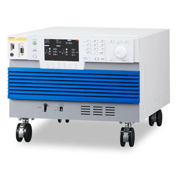
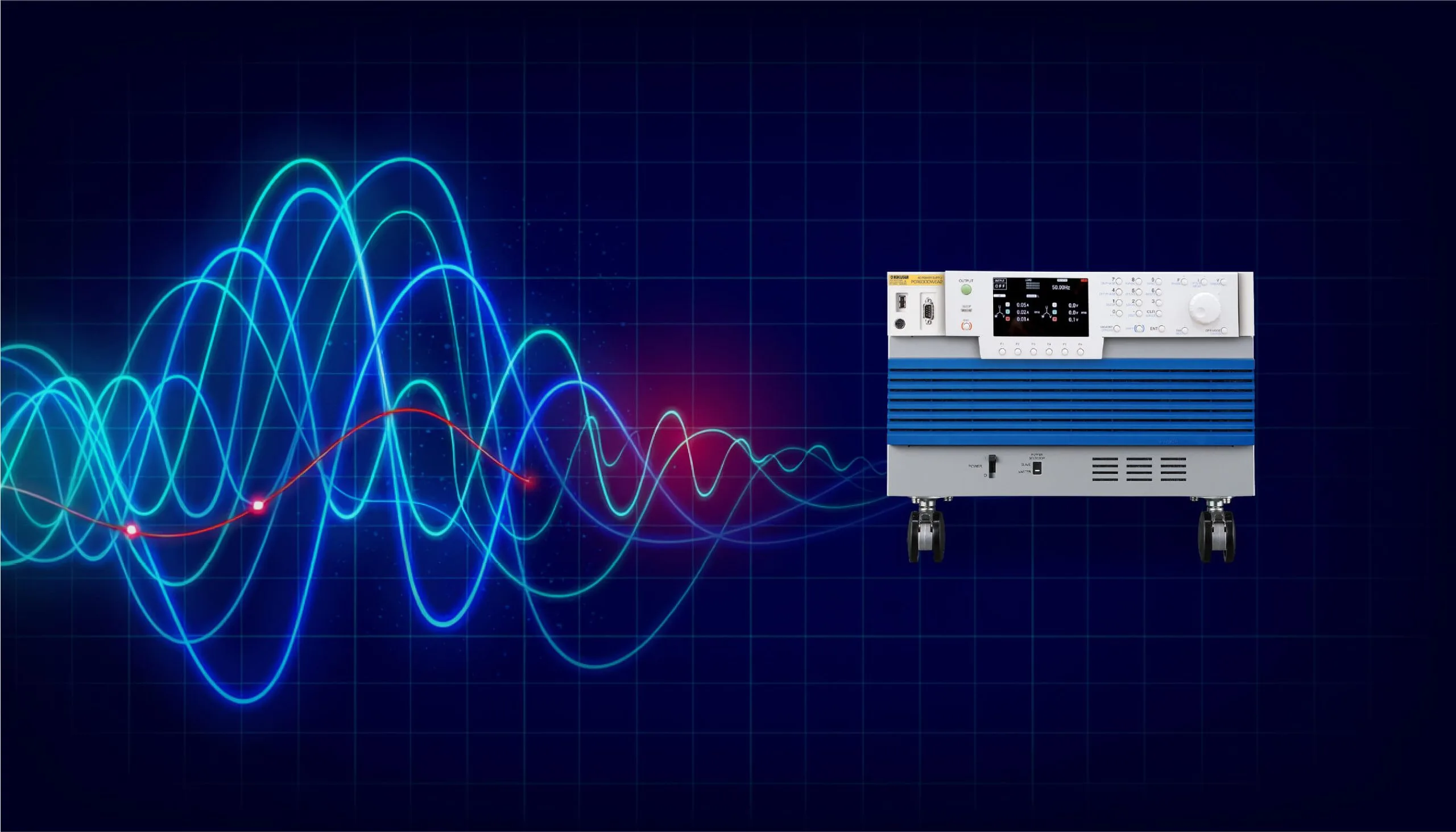
The Kikusui PCR6000WEA2 — 6 kVA in 6U. The PWM inverter output synthesizes the flat-curve, over-swing, and multi-component waveforms of IEC 61000-4-13 directly, with intrinsic THD as low as 0.3 % and independent per-phase control in three-phase mode.
| Requirement of the standard | PCR-WEA2 implementation |
|---|---|
| Fundamental voltage and frequency stability | AC voltage accuracy ±(0.3 % of setting + 0.3/0.6 V); frequency accuracy ±0.01 % with 0.01 Hz resolution below 100 Hz — comfortably inside the Table 5 tolerances |
| Distorted-waveform synthesis | Arbitrary/harmonic waveform programming; flat curve, over-swing, and combined-component waveforms generated directly by the PWM inverter |
| Band to 2.4 kHz with phase control | Output frequency range 1 Hz–5,000 Hz (>2× headroom); output phase resolution 0.01–0.1° up to 500 Hz, 1° to 4 kHz |
| Low intrinsic distortion | THD ≤0.3 % (to 100 Hz), ≤0.5 % (100.1–330 Hz), ≤1.5 %/kHz above 330 Hz |
| Defined phase displacement between phases (three-phase) | Independent per-phase control; single-phase / single-phase three-wire / three-phase switchable (3 kVA multi-type models and above) |
| 16 A per phase at nominal voltage | Model range 1–36 kVA: L-range currents 10–360 A rms; peak capability 4× rating (crest factor 4) for distorted-current EUTs |
| All -4-13 test types, automated | SD009-PCR-LE/WE: flat curve, over-swing, sweep in frequency, odd/even harmonics, interharmonics, and Meister curve — listed by Kikusui as fully supported in both single-phase and three-phase configurations; chained sequences, waveform preview, txt/csv export |
| Verifying the applied waveform | Built-in harmonic analysis to the 50th order (4,096-point FFT) — the source measures what it applies |
Because the same PCR-WEA2 + SD009 platform also executes IEC 61000-4-11/-4-34 dips, -4-14 voltage fluctuations, -4-27 unbalance, -4-28 frequency variations, and the DC-port tests (-4-17, -4-29), a lab covers the complete low-frequency conducted immunity suite with one instrument and one software environment — and keeps a general-purpose 5 kHz grid simulator between compliance campaigns.
SD009 Test-Item Coverage for IEC 61000-4-13
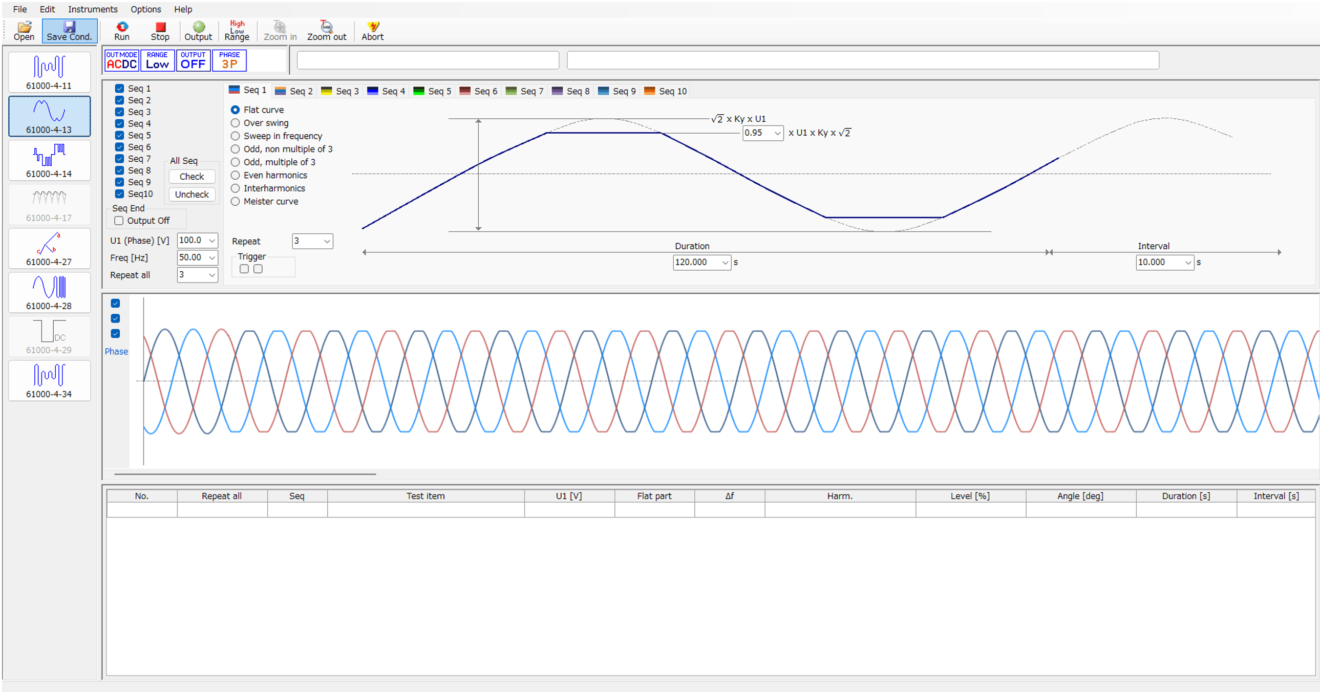
SD009 is formally titled “Quick Immunity Sequencer 2” (QIS2); its conformance list (QIS2 Operation Guide, which references IEC 61000-4-13 Edition 1.2, 2015-12) shows every -4-13 test item with full support (“✓”) in both single-phase and three-phase configurations: flat curve, over-swing, frequency sweep, odd harmonics (non-multiple and multiple of 3), even harmonics, interharmonics, and Meister curve. Execution features that matter for this standard specifically: dual preliminary/compliance modes (probe beyond class levels during development, lock to the tables for the formal run), chaining of up to 10 sequences (the full class campaign — pre-tests, sweep, retests, individual orders at 0°/180°, signalling — runs unattended), waveform preview before application, and txt/csv export of settings and results. Operating environment: Windows 10/11 with a VISA layer (KI-VISA, NI-VISA, or Keysight IO Libraries) over LAN, USB, or RS-232C; firmware prerequisites are PCR-WEA/WEA2 v3.10+, PCR-WE/WE2 v1.32+, PCR-LE v4.0+. The QIS2 window presents a per-standard selection pane, a test-conditions pane, a live waveform preview, and a result list.
Selecting the Right Model
| Typical EUT | Key sizing figures | Suggested configuration |
|---|---|---|
| Appliance / ITE / charger, ≤16 A at 230 V (formal -4-13 scope) | ≤3.7 kVA; distorted-current crest factor under distorted voltage | PCR3000WEA2 or PCR6000WEA2 — 30/60 A L-range with 4× peak headroom |
| Metering / smart-meter test station | Precision fundamental plus programmable components; long automated campaigns | PCR1000WEA–PCR3000WEA2 with SD009; built-in 50th-order FFT closes the verification loop |
| Three-phase EUT (engineering tests at -4-13 waveshapes) | Independent per-phase synthesis with software-switchable 1φ / 1φ3W / 3φ output; three-phase derating | PCR6000WEA2 multi-type and above (software-switchable 1φ/1φ3W/3φ) |
| Large equipment beyond 16 A (engineering practice) | Rated current per phase; waveform fidelity at power | PCR12000WEA2–PCR36000WEA2; parallel operation beyond 36 kVA |
A Step-by-Step Test Workflow
- Classify: confirm ≤16 A per phase scope, select the class (2/3/X per the product standard), and the performance criteria per test.
- Pre-tests: apply the flat-curve and over-swing composites (Tables 7/8) — quick screens that catch peak-detection and timing sensitivities early.
- Sweep: run the quasi-stationary frequency sweep across 0.33·f₁ to the 40th harmonic at class level, logging EUT current; record every anomaly frequency.
- Resonance retests: retest each recorded frequency at the harmonic/interharmonic table levels with dwell.
- Individual orders: apply harmonics 2–40 at class levels — twice (0°/180°) for components ≥3 % up to the 9th order.
- Signalling: apply the Meister-curve levels (Class 2).
- Report: criteria per test item, anomaly log from the sweep, and the applied-spectrum verification from the built-in FFT — exported via SD009.
Questions & Answers
About the Standard
Q. How is IEC 61000-4-13 different from harmonic emissions testing (IEC 61000-3-2 / -3-12)? A. Direction. Emissions standards limit the distorted current a product injects into the network; -4-13 is immunity — it distorts the supply voltage on purpose and checks that the product still works. A complete AC-port program needs both, but note that they are different benches: emissions measurement feeds the EUT through a defined reference impedance so that the voltage distortion the EUT causes is evaluated against a standardized network. Kikusui builds that station from a PCR-LE-family supply plus a LIN-series line impedance network (LIN1020JF/LIN3020JF at 20 A per phase; LIN3060J at 60 A per phase) and the KHA3000 harmonic/flicker analyzer. The LIN’s selectable elements are Z1 for JIS 100 V harmonic testing, Z2 for JIS 200 V, and Z3 for IEC flicker testing, and they can be bypassed where the applicable edition makes the impedance optional. Two details of the published values are worth understanding rather than reading as misprints. First, Z1 and Z2 are identical on the line phase — both 0.19 Ω + 0.23 mH — because the two cases differ in the neutral, not the line: Z1 uses 0.21 Ω + 0.14 mH on N for single-phase two-wire circuits, while Z2 uses 0.19 Ω + 0.23 mH on N for single-phase three-wire and three-phase circuits. Second, Z3 is quoted as a complex impedance — 0.24 Ω + j0.15 Ω on the line and 0.16 Ω + j0.10 Ω on the neutral — rather than as resistance plus inductance, because it is the flicker reference impedance of IEC 61000-3-3 / IEC TR 60725, which that standard defines as R + jX at the fundamental. Kikusui’s published compliance-test-system configuration for the PCR-WEA/WEA2 covers the emissions standards IEC 61000-3-2/-3-12 and IEC 61000-3-3/-3-11 alongside the -4-x immunity family on the same platform, with the LIN (and the DSI dip simulator) supplied as specially made-to-order items for that combination — so a WEA2-based laboratory can add the emissions station without changing supply families. Specify the intended combination with the order.
Q. Why interharmonics and a swept test, not just integer harmonics? A. Drives and cycloconverters generate components between integer orders, and network/filter resonances are narrow. A slow quasi-stationary sweep with dwell walks through the passbands of filters and PLLs and exposes resonances that spot tests at integer orders would miss.
Q. Why are some harmonics applied at both 0° and 180°? A. The phase of a harmonic relative to the fundamental determines whether it flattens or peaks the composite waveform — two different stress mechanisms at the same magnitude. The standard therefore requires both phases for components ≥3 % of U₁ up to the 9th order, referenced to the positive zero-crossing of the fundamental.
Q. Which products actually have to run this test? A. IEC 61000-4-13 is invoked selectively by product committees (for example in metering and some industrial and appliance standards) rather than blanket-required like -4-11. Check your product standard’s immunity table — and note that Class X provisions let committees tailor levels, with Class 2 as the floor for equipment on public supplies.
Q. Does the 16 A scope limit mean large equipment is never tested? A. Formally yes — the standard applies at ≤16 A per phase, and 16⅔ Hz / 400 Hz networks are excluded entirely. In practice the same waveforms are widely applied to larger equipment as engineering tests; the PCR-WEA2 scales to 36 kVA per unit (parallel beyond) to support this.
Test Practice
Q. What happens when the sweep finds a resonance? A. Frequencies at which the EUT’s current or behavior shows anomalies are recorded during the sweep, and the EUT is then retested at those specific frequencies at the harmonic-table levels with dwell — the sweep is a search procedure, the retest is the verdict. Skipping the retest step is a common test-plan error.
Q. How long does a full -4-13 campaign take? A. Hours, not minutes: the band up to 2/2.4 kHz is swept in small steps with dwell at each step, individual harmonics are applied order by order (twice, for the 0°/180° cases at ≥3 %), and composite and signalling tests follow — per phase configuration. This is why scripted automation (SD009 chains up to 10 sequences) and waveform preview without an oscilloscope materially change the cost of the test.
Q. What performance criteria apply during the distortion? A. The familiar EMC criteria A–D, assigned per test by the product standard. Note the scope boundary: effects requiring more than 15 minutes of exposure (thermal) are outside -4-13 — if a harmonic level causes slow heating, that is assessed by other means.
Q. How do I verify the generator is actually applying the right waveform? A. Clause 6 requires set values to be met at the EUT terminals. The PCR-WEA2’s built-in 50th-order harmonic analysis (4,096-point FFT) measures the applied spectrum at the output, and SD009’s waveform preview shows the composite before it is applied — closing the loop without external instrumentation.
Equipment Selection
Q. Can a standard programmable AC source run the flat-curve test? A. Only if it supports arbitrary waveform synthesis with the RMS held at nominal while the peak is clipped — sine-only sources with amplitude modulation cannot generate the required waveshapes. Bandwidth headroom also matters: accurate 2.4 kHz components with controlled phase need an output stage rated well beyond 2.4 kHz (the PCR-WEA2 reaches 5 kHz).
Q. Three-phase EUT — what changes? A. The generator must superimpose components independently on each phase while holding the specified displacement between the phase fundamentals. The PCR-WEA2 multi-type models provide per-phase waveform control in three-phase mode, and Kikusui’s support matrix lists all -4-13 test types as supported in both single-phase and three-phase configurations.
Conclusion
IEC 61000-4-13 exercises a failure mode that clean-sine testing never touches: equipment behavior on the polluted networks it will actually meet. Its substance is precision waveform synthesis — order-by-order harmonic levels at controlled phase, band-by-band interharmonics, clipped and over-swung composites at nominal RMS, slow resonance-hunting sweeps, and signalling tones — plus the automation to step through classes, orders, and phases without operator error. The Kikusui PCR-WEA/WEA2 Series provides the synthesis engine (5 kHz bandwidth, 0.3 % intrinsic THD, per-phase control, 4× peak current) and SD009 provides full test-type coverage, within the same platform that runs the rest of the IEC 61000-4-x low-frequency immunity family. For details or a demonstration, contact Kikusui America at kikusuiamerica.com.