Executive Summary
- IEC 61000-4-11 (Edition 3.0, 2020) defines immunity test methods for voltage dips, short interruptions, and voltage variations on equipment drawing 16 A or less per phase from 50/60 Hz networks. IEC 61000-4-34 (2005, amended 2009; EN amendment A2:2025) extends the same phenomena to equipment drawing more than 16 A per phase — in practice, most three-phase industrial equipment. Both are invoked by the generic and product EMC immunity standards used for CE marking.
- The standards are demanding on the test generator, not just the EUT: voltage transitions must complete in 1–5 µs (measured into a 100 Ω resistive load), dips must start at a defined phase angle, three-phase dips must be applied to individual line-to-neutral and line-to-line voltages, and the source must drive the EUT’s full recovery inrush current (a capability requirement of up to 500 A peak for 220–240 V mains in IEC 61000-4-11).
- The Kikusui PCR-WEA/WEA2 Series (1–36 kVA single unit; peak current 4× rating; transient response 40 µs typical in FAST mode) together with the SD009-PCR-LE/WE “Quick Immunity Sequencer 2” (QIS2) software executes the dip, interruption, and variation profiles of both standards for development and preliminary testing, and covers the surrounding immunity family (IEC 61000-4-13, -4-14, -4-17, -4-27, -4-28, -4-29) on the same platform. Where the strict 1–5 µs switching-time requirement of the standards must be met for full compliance, Kikusui supports combining the software with a dedicated IEC dip simulator (DSI series) — this paper explains exactly where that boundary lies.
What Are IEC 61000-4-11 and IEC 61000-4-34?
IEC 61000-4-11:2020, “Testing and measurement techniques — Voltage dips, short interruptions and voltage variations immunity tests for equipment with input current up to 16 A per phase,” establishes a common reference for evaluating immunity to sudden reductions and losses of the AC supply voltage. IEC 61000-4-34 applies the same phenomena to equipment with rated input current above 16 A per phase, including three-phase equipment on public low-voltage networks.
The standards define the phenomena precisely. A voltage dip is a sudden reduction of the voltage below a threshold, followed by recovery after a short interval — typically caused by short circuits elsewhere in the network or by sudden large current increases. A short interruption is the reduction of voltage on all phases below an interruption threshold — typically associated with switchgear operation and fault clearing. The residual voltage is the minimum RMS voltage recorded during the event, expressed as a percentage of the rated voltage UT. Edition 3.0 formally defines the transition rise time tr and fall time tf as the interval between the 10 % and 90 % points of the change.
Equipment Classes
Test levels are selected by installation environment class, following the classification of IEC 61000-2-4: Class 1 — protected supplies (levels defined case-by-case for the equipment); Class 2 — points of common coupling with the public network and general industrial connection points; Class 3 — in-plant connection points in industrial environments, where a higher severity applies (e.g., presence of large drives, welding machines, frequently switched heavy loads); Class X — levels agreed between manufacturer and user or set by product committees.
Test Levels (IEC 61000-4-11:2020, Tables 1 and 2; identical philosophy in IEC 61000-4-34)
| Test | Residual voltage (% of UT) | Duration (50 Hz / 60 Hz) | Applies to |
|---|---|---|---|
| Voltage dip | 0 % | 0.5 cycle | Class 2 and Class 3 |
| Voltage dip | 0 % | 1 cycle | Class 2 and Class 3 |
| Voltage dip | 40 % | 10 / 12 cycles | Class 3 |
| Voltage dip | 70 % | 25 / 30 cycles | Class 2 and Class 3 |
| Voltage dip | 80 % | 250 / 300 cycles | Class 3 |
| Short interruption | 0 % | 250 / 300 cycles (≈5 s) | Class 2 and Class 3 |
| Class 1 / Class X | Case-by-case | Case-by-case | Per equipment / product committee |

Figure 1. IEC 61000-4-11:2020 test points by equipment class: residual voltage versus event duration (60 Hz cycle counts shown). Class 3 (industrial in-plant) adds the 40 % / 10–12-cycle and 80 % / 250–300-cycle dips to the Class 2 set. Source: IEC 61000-4-11:2020 Tables 1 and 2.
The voltage variation test (optional, applied where the product standard requires it) uses a defined profile at the 70 % level: an abrupt decrease to the test level, 1 cycle at the reduced voltage, and a gradual recovery over 25/30 cycles (50/60 Hz) back to the rated voltage.

Figure 2. The voltage variation profile of IEC 61000-4-11:2020 Table 3: abrupt decrease to 70 % of UT, one cycle at the reduced level, then a gradual ramp back over 25/30 cycles — a regulation-style event, distinct from the rectangular dip.
How the Tests Are Applied
Number of Events, Intervals, and Phase Angle
- Each selected combination of level and duration is applied as a sequence of three dips or interruptions, with an interval of at least 10 s between events, in the EUT’s representative operating mode.
- Voltage changes occur at zero crossings of the voltage, and additionally at the phase angles considered critical by the responsible product committee, preferably selected from 45°, 90°, 135°, 180°, 225°, 270°, and 315° on each phase. The phase angle changes the flux and charge conditions in the EUT input stage at the moment of the event, so it is a controlled test parameter — not an accident of timing.

Figure 3. The same 40 % dip started at 0° (zero crossing) and at 90° (voltage peak). The onset angle determines the instantaneous conditions in the EUT’s input rectifier and any transformer magnetics, so the standards make it a programmable, reported parameter.
Three-Phase Application Rules
For three-phase equipment, dips are not simply applied to all phases at once:
- Equipment with neutral: each phase-to-neutral voltage and each phase-to-phase voltage is tested individually — six test series in total.
- Equipment without neutral: each phase-to-phase voltage is tested individually — three test series.
- Short interruptions: applied to all phases simultaneously, reflecting their switchgear-related origin.

Figure 4. A dip applied to one phase of a three-phase system. Testing individual line-to-neutral and line-to-line voltages requires independent per-phase amplitude control in the test source.
Measured Waveforms: Line-Voltage Dips on a Real Three-Phase System
The captures below were taken in Kikusui’s laboratory on a three-phase test system driven by a PCR-series programmable AC power supply alone — no DSI dip simulator in the circuit — i.e., the configuration the support matrix classifies as preliminary testing. The oscilloscope measures the three line-to-line voltages (CH1 = R–S, CH2 = S–T, CH3 = T–R, delta measurement). Line-voltage dips are generated by phase-angle displacement: shifting the voltage vector of one phase (the standard’s preferred method, (A)) or of two phases (the permitted alternative, (B)) collapses the targeted line voltage to the residual value. Two points worth noting: the characteristic cusps on the adjacent line voltages at the switching instants are the vector recombination itself, not a source artifact; and a dip applied to one voltage changes the other line voltages too — which is precisely why IEC 61000-4-34 requires each line-to-line and line-to-neutral case to be tested individually. What these captures demonstrate, therefore, is that the PCR source by itself already produces the complete three-phase dip patterns of both methods — level, duration, phase selection, and onset control. What the DSI pairing adds on top is the certified 1–5 µs switching edge (and the 500 A peak drive) that Table 4 requires for formal compliance.
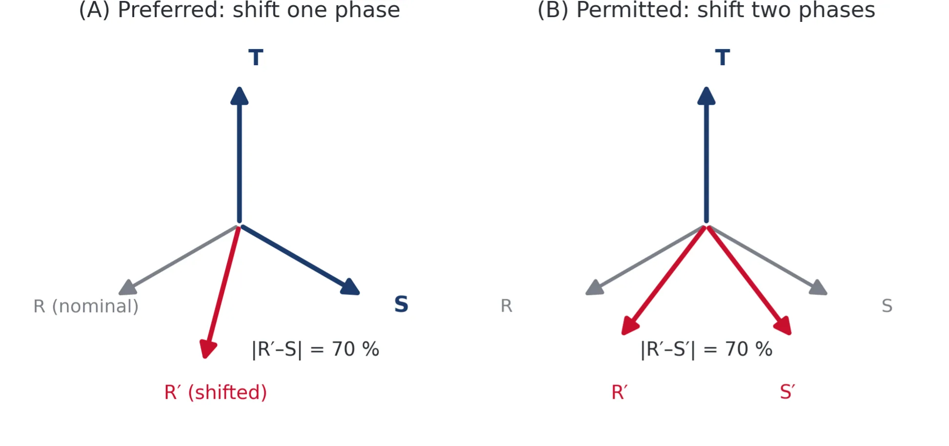
Figure 5. How a line-voltage dip is generated by phase displacement, after the standard’s method illustration: (A) preferred — one phase vector is shifted until the targeted line voltage reaches the residual level (70 % shown); (B) permitted — two phase vectors are shifted symmetrically to the same effect. Both are demonstrated in the measured captures below.
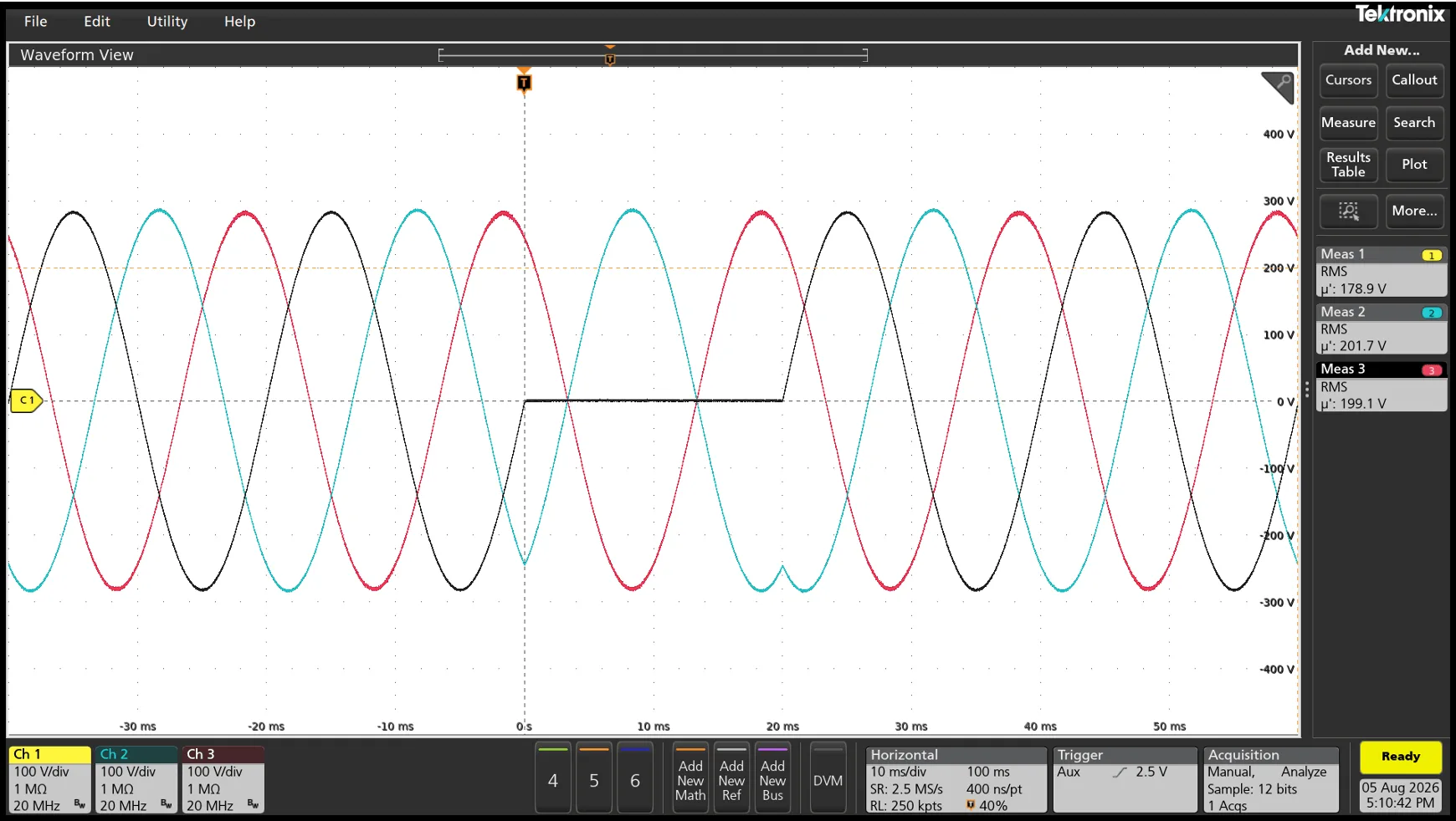
Figure 6. Measured (method A — one phase shifted): 0 % dip of the R–S line voltage for 1 cycle (delta measurement; CH1 = R–S, CH2 = S–T, CH3 = T–R). The targeted line voltage collapses completely while the other two continue, with visible cusps at the transitions. RMS readouts over the measurement window: 178.9 V / 201.7 V / 199.1 V on a 200 V system.

Figure 7. Measured (method A): entry into a 70 % dip generated by single-phase displacement. The RMS readouts show the asymmetric effect on the three line voltages — 166.6 V, 188.3 V, 198.9 V on a 200 V system — a dip applied to one voltage is never “clean” on the others.
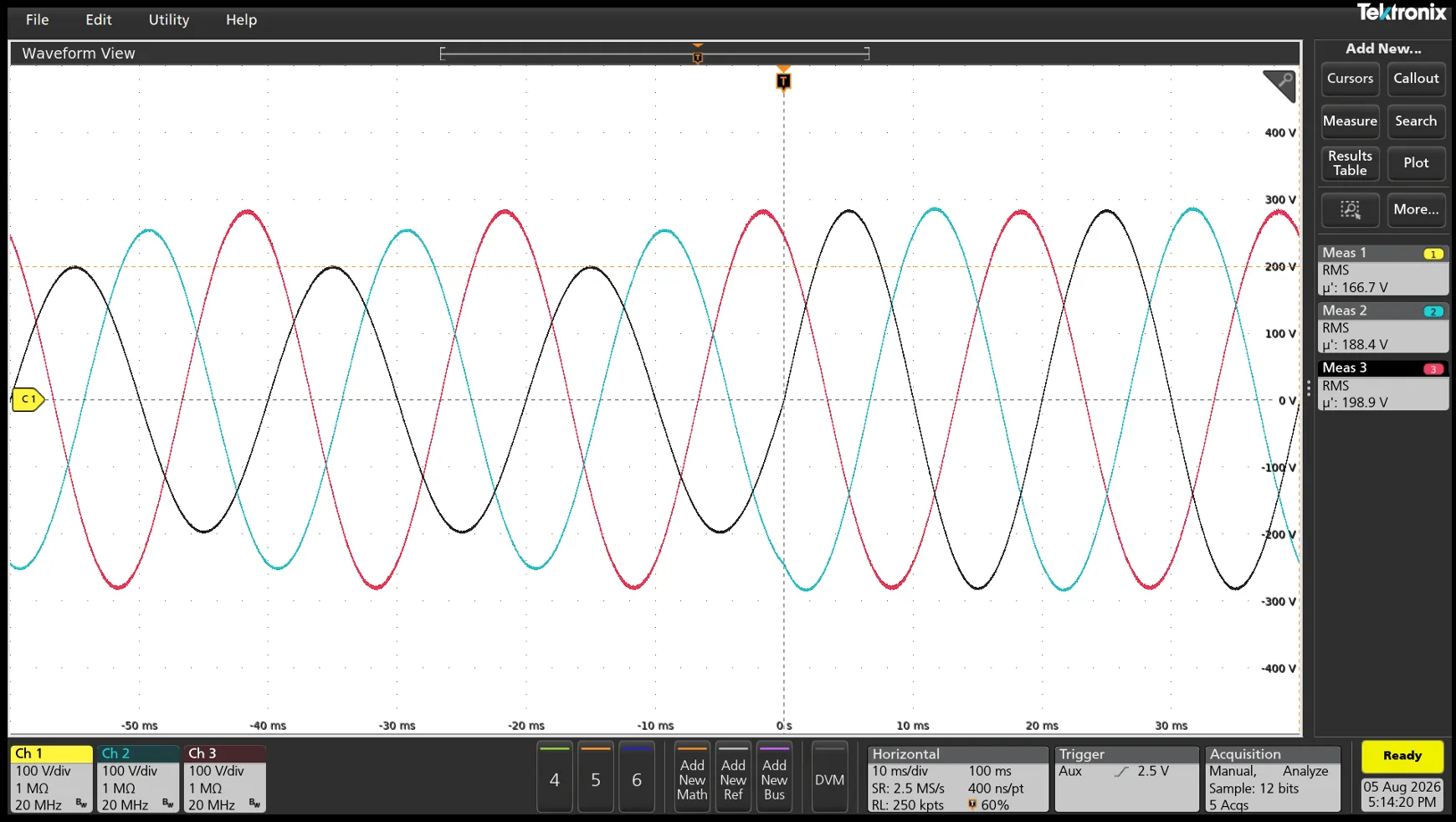
Figure 8. Measured (method A): recovery at the end of the same 70 % dip. Entry and exit both occur at controlled phase angles, and the un-dipped line voltages return to nominal without overshoot.
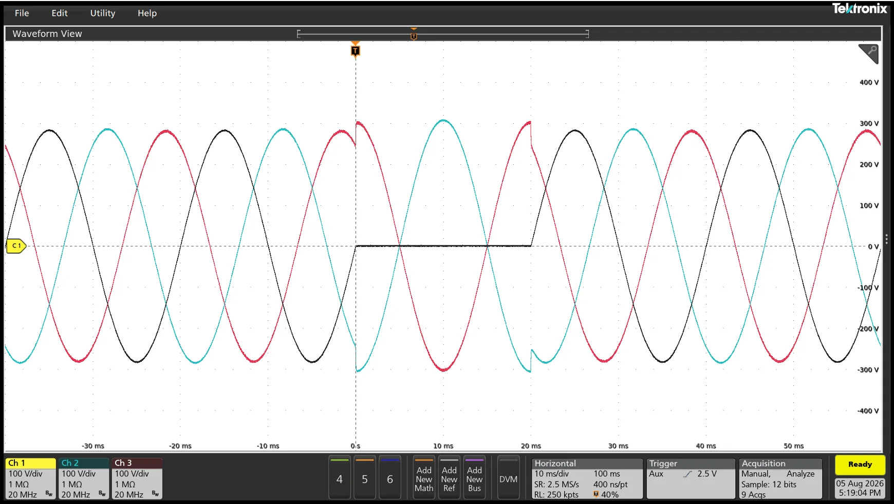
Figure 9. Measured (method B — two phases shifted): the same 0 % / 1-cycle dip of the R–S line voltage generated by displacing two phase vectors. The disturbance signature on the adjacent line voltages differs from method A — symmetric step-and-cusp features on both S–T and T–R — which is why the standard states a preference: the two methods stress the EUT differently even at identical residual voltage.
Performance Criteria
The EUT’s behavior during and after each event is classified against the familiar EMC performance criteria: A — normal performance within specified limits; B — temporary degradation that self-recovers; C — temporary degradation requiring operator intervention or system reset; D — non-recoverable degradation or loss of function (equipment damage, firmware corruption). Which criterion is acceptable at which test level is assigned by the relevant generic or product standard, not by IEC 61000-4-11/-4-34 themselves.
Generator Requirements — the Hard Part of the Standard
Clause 6 of each standard specifies the test generator. Three requirements dominate equipment selection:
1. Switching Speed: 1–5 µs
Per IEC 61000-4-11 Ed. 3 (6.1.2, Table 4) and IEC 61000-4-34 (6.1.1, Table 4), the voltage rise and fall time during the abrupt change, with the generator loaded by a 100 Ω resistive load, must be between 1 µs and 5 µs — with overshoot/undershoot limited to a few percent. This microsecond-scale transition reproduces the near-instantaneous voltage collapse of a real short circuit and stresses input rectifiers and EMI filters realistically. IEC 61000-4-34 keeps the same 1–5 µs requirement for EUTs up to 75 A per phase and permits up to 50 µs above 75 A per phase.
This requirement is historically met by switching between two transformer taps (or two sources) with fast semiconductor switches. It matters when selecting equipment, because a PWM programmable source transitions in tens of microseconds — see “Compliance boundaries” below.

Figure 10. The switching-edge distinction, drawn to scale in microseconds: a switched dip generator (DSI class) completes the transition in 1–5 µs and satisfies Table 4; a PWM programmable source transitions in ~40 µs — far faster than real network events, and accepted for preliminary and margin testing, but outside the strict Table 4 window.
2. Inrush Current Drive Capability
When the voltage recovers, the EUT’s rectifier recharges its DC bus capacitors in a few half-cycles, drawing far more than rated current. IEC 61000-4-11 requires the generator to be capable of driving a peak inrush current of up to 500 A for 220–240 V mains (with a correspondingly lower requirement, 250 A, for 100–120 V mains). Edition 3 pragmatically allows a generator of lower capability to be used where the EUT’s actual peak inrush has been measured and shown to be within the generator’s capability. Under IEC 61000-4-34 the drive requirement scales with the EUT rating — dip-generator specifications for this standard are typically in the 1,000 A (half-wave peak) to 2,000 A (short-circuit) region.

Figure 11. Why inrush capability is a generator requirement: at recovery from an interruption, the EUT’s rectifier recharges its DC bus, drawing several times rated current for the first half-cycles. A source that current-limits here changes the very phenomenon under test. The PCR-WEA2’s 4× peak-current rating (crest factor 4) is sized for exactly this moment.
3. Steady-State Quality
The generator must hold the rated voltage within a few percent, keep distortion low, and apply the specified residual voltages accurately at the EUT terminals — while delivering rated current continuously and the inrush peaks transiently.
Running the Tests with the Kikusui PCR-WEA2 Series
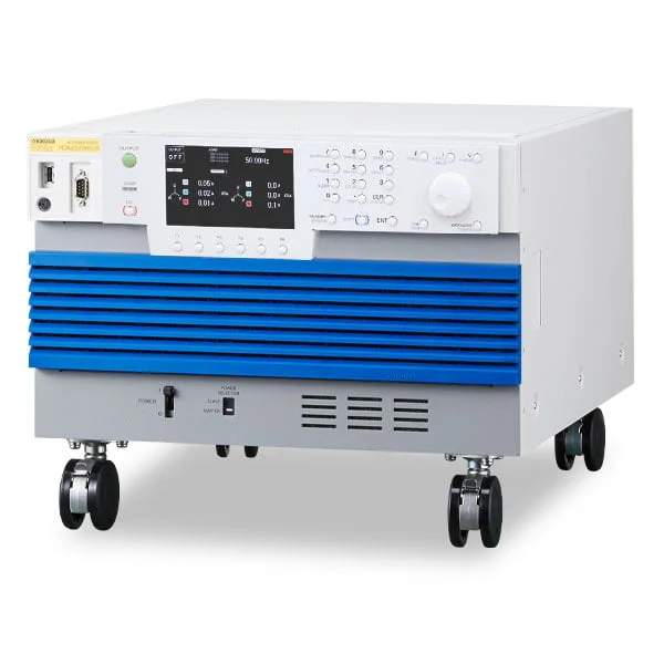
The Kikusui PCR6000WEA2 — 6 kVA in a 6U chassis. Multi-type models switch between single-phase, single-phase three-wire, and three-phase output under software control, deliver 4× rated peak current (crest factor 4), and respond in 40 µs typical (FAST mode).
The PCR-WEA/WEA2 Series is an ultra-compact PWM inverter AC/DC programmable power supply: 1–36 kVA in a single unit (6 kVA in 6U), AC output 0–160 V / 0–320 V per phase, DC to ±452 V, 1 Hz–5 kHz, with single-phase / single-phase three-wire / three-phase output switchable by software on multi-type models (3 kVA and above). Key figures relevant to dip testing:
| Parameter | PCR-WEA/WEA2 specification |
|---|---|
| Peak current capability | 4× the maximum output current (repetitive at crest factor 4) — e.g., 240 A peak on a PCR6000WEA2 in the L range (60 A rms) |
| Transient response | 40 µs typical (FAST mode); 100 µs (MEDIUM); 300 µs (SLOW) |
| AC voltage accuracy | ±(0.3 % of setting + 0.3 V / 0.6 V) |
| Frequency accuracy / resolution | ±0.01 %; resolution 0.01 Hz (1–100 Hz), 0.1 Hz (100–1,000 Hz), 1 Hz (1,000–5,000 Hz) |
| Output phase resolution | 0.01–0.1° (to 500 Hz); waveform THD ≤0.3 % (to 100 Hz), ≤0.5 % (100.1–330 Hz) |
| Disturbance simulation | Built-in dip/swell (pop)/interruption simulation with programmable depth, duration, and onset phase angle; sequence function for chained profiles |
| Maximum currents by model | L range: 10 A (1 kVA) → 360 A (36 kVA); H range: half of L-range values; three-phase and 1φ3W modes at reduced per-phase ratings |
| Interfaces / automation | LAN (LXI), USB, RS232C standard, GPIB optional; SD009 software; web-browser control |
SD009-PCR-LE/WE Software Coverage — the Published Support Matrix
Kikusui publishes an explicit, test-item-level support matrix for SD009 with the PCR-WE/WEA families (“✓” = full support; “▲” = preliminary/limited). This transparency is itself a selection criterion — it tells you before purchase exactly which runs are compliance-grade:
| Standard | Test items in SD009 | Support level |
|---|---|---|
| IEC 61000-4-11 (Ed. 3.0, 2020) | Voltage dips; short interruptions; voltage variations | Dips/interruptions: ✓ full compliance with DSI1020/DSI3020 dip simulator, ▲ preliminary with PCR alone; variations: ✓ full (single- and three-phase) |
| IEC 61000-4-34 (Ed. 1.1, 2009) | Voltage dips; short interruptions; voltage variations (>16 A/phase) | ▲ preliminary for 16–75 A EUTs (1–5 µs change required); above 75 A the requirement relaxes to 1–50 µs; variations ✓ full |
| IEC 61000-4-13 (Ed. 1.2, 2015) | Flat curve, over-swing, frequency sweep, odd harmonics (non-multiple/multiple of 3), even harmonics, interharmonics, Meister curve | ✓ fully supported, single- and three-phase |
| IEC 61000-4-14 | Voltage fluctuations (swing/interval) | ✓ full, single- and three-phase |
| IEC 61000-4-17 | Ripple on DC input — single-phase and three-phase rectifier waveshapes | ✓ (DC output configuration) |
| IEC 61000-4-27 | Three-phase voltage unbalance | ▲ preliminary — the voltage steps (110/95.2/93.5/90/87/80/74/71/66 % of rated) must change in 1–5 µs; PCR-WE response is 40 µs at FAST |
| IEC 61000-4-28 | Frequency variations | ✓ full, single- and three-phase |
| IEC 61000-4-29 | DC dips, short interruptions, variations | Dips ✓ (PCR-LE) / ▲ (PCR-WE); variations ✓; short interruptions ▲ (the open state requires source impedance >100 kΩ) |
Operating environment and practical notes: SD009 is formally titled “Quick Immunity Sequencer 2” (QIS2). Firmware prerequisites: PCR-WEA/WEA2 (including WEA2R) version 3.10 or later; PCR-WE/WE2 version 1.32 or later (2.00+ recommended — FAST-mode response is 55 µs below 2.00); PCR-LE version 4.0 or later. Windows 10/11 (8 GB RAM minimum, 16 GB recommended); connects over LAN, USB, or RS-232C via VISA (NI-VISA 5.0.3+, Keysight IO Libraries 16.1+, or Kikusui KI-VISA 5.0.5+); dual-mode execution — a preliminary/margin mode for exploring severity beyond the table levels and a compliance mode locked to the standard; up to 10 sequences chained per run; waveform preview before execution (no oscilloscope needed to sanity-check a profile); settings and results exported to txt/csv for the report file.

The DSI1020 / DSI3020 Dip Simulator — the Full-Compliance Path
For strictly conformant switching edges, Kikusui’s DSI1020 (single-phase) and DSI3020 (single-phase / single-phase three-wire / three-phase 3- and 4-wire) dip simulators insert a high-speed semiconductor switching stage between one or more PCR-LE/WE-family supplies and the EUT. QIS2 controls the complete system, so the workflow is identical to PCR-alone testing — the DSI simply supplies the microsecond edge. Verified performance from the DSI operation manual:
| DSI1020 / DSI3020 parameter | Specification |
|---|---|
| Compliant standard | IEC 61000-4-11 Ed. 3.0 (2020); dip levels 0 %, 40 %, 70 %, 80 % |
| Dip source | DSI1020: phase voltage (1P2W); DSI3020: phase voltage and line voltage (1P2W/1P3W/3P3W/3P4W — 230 V three-phase four-wire and 400 V line-voltage systems) |
| Voltage rise / fall time | 1 µs to 5 µs (10–90 %, 100 Ω load) — exactly the Table 4 window |
| Overshoot / undershoot | < 5 % of UT |
| Maximum output current | 16 Arms/phase at 100 % UT; 40 Arms/phase at 40 % UT; 500 A peak (≤1 s) — meeting the standard’s inrush-drive requirement |
| Phase angle of onset | 0°–360° in 45° steps (0/45/90/135/180/225/270/315/360°), setting accuracy <10° |
| Dip duration setting | 0.5, 1, 5, 10, 25, 50 cycles and any 2–300 cycles (1-cycle resolution) |
| Event interval | 10–99 s settable (default 10 s) |
| Maximum input | 288 Vrms phase voltage; 500 Vrms line voltage / 700 Vpeak (DSI3020) |
| Monitoring / control | BNC voltage monitor (1 V/100 V) and current monitor (1 V/100 A), trigger in/out; RS-232C standard, USB factory option (QIS2 v4.0+) |
System output capacity depends on the paired AC supply and wiring (the DSI manual tabulates per-phase capacities for PCR-LE combinations at 100/230 V single-phase and 200/400 V three-phase; for PCR-WE-family pairings, consult Kikusui).
The Complete Compliance Test System: Immunity and Emissions on One Platform
Immunity is only one side of a conducted-EMC program, and the PCR-WEA/WEA2 platform is designed to cover both. Kikusui’s published system configuration for standard compliance testing combines the PCR-WEA/WEA2 AC power supply, the KHA3000 harmonic/flicker analyzer, a LIN-series line impedance network, a DSI-series IEC dip simulator, and the application software into a single rack-based station — available in single-phase and three-phase configurations. The standards this system addresses:
| Standard | Phenomenon tested |
|---|---|
| IEC 61000-4-11 | Voltage dips, instantaneous power failure, and voltage variation |
| IEC 61000-4-13 | Harmonics and interharmonics |
| IEC 61000-4-14 | Voltage fluctuation |
| IEC 61000-4-27 | Voltage unbalance |
| IEC 61000-4-28 | Power-supply frequency variation (equipment to 16 A/phase) |
| IEC 61000-4-34 | Voltage dips, instantaneous power failure, and voltage variation (input current exceeding 16 A/phase) |
| IEC 61000-4-17 | Ripple at the DC input power terminal |
| IEC 61000-4-29 | Voltage dips, instantaneous power failure, and voltage variation on DC (preliminary test purposes) |
| IEC 61000-3-2 / -3-12 | Harmonic current emission limits |
| IEC 61000-3-3 / -3-11 | Voltage fluctuation and flicker limits |

Figure 12. The compliance test system as delivered: single-phase and three-phase rack configurations. The PCR-WEA/WEA2 supplies the simulated grid, the DSI provides the standard-conformant dip switching, the LIN presents the reference impedance for emissions measurement, and the KHA3000 measures harmonic current and flicker.

Figure 13. The standard compliance test system built on the PCR-WEA/WEA2: the AC supply reproduces the grid and its abnormalities, the DSI supplies the standard-conformant switching edge for dip testing, the LIN presents the reference impedance for emissions measurement, and the KHA3000 measures harmonic current and flicker. Single-phase and three-phase configurations are available; the LIN and DSI are specially made-to-order items in combination with the PCR-WEA/WEA2 Series.
The last two rows are the emissions side — harmonic current limits (IEC 61000-3-2 / JIS C 61000-3-2) and flicker (IEC 61000-3-3) of the same program: harmonic current limits and flicker are measured with the EUT fed through a defined reference impedance, so that the disturbance the EUT causes is evaluated against a standardized network rather than whatever the laboratory supply happens to present. That reference impedance is the LIN. Its per-phase elements are switch-selectable and can be shorted out (BYPASS) when the applicable edition of the standard makes the impedance optional:
| Model | Rated current | Impedance selections (per phase) | Purpose / wiring systems |
|---|---|---|---|
| LIN1020JF (1φ) / LIN3020JF (1φ and 3φ) / OP01-LIN1020JF (adds 3φ to LIN1020JF) | 20 A per phase | Z1 = 0.19 Ω + 0.23 mH; Z2 = 0.19 Ω + 0.23 mH; Z3 = 0.24 Ω + j0.15 Ω (N phase: 0.21 Ω + 0.14 mH / 0.19 Ω + 0.23 mH / 0.16 Ω + j0.1 Ω); BYPASS shorts the element | Z1: JIS 100 V harmonic test · Z2: JIS 200 V harmonic test · Z3: IEC flicker test. 1P2W / 1P3W / 3P3W / 3P4W |
| LIN3060J | 60 A per phase | Z1 = 0.19 Ω + 0.23 mH; Z2 = 0.19 Ω + 0.23 mH (N phase: 0.21 Ω + 0.14 mH / 0.19 Ω + 0.23 mH); BYPASS shorts the element | Reference impedance for JIS/JET grid-interconnection testing of power conditioners (JETGR0002-1-2.0) and for higher-current harmonic testing. Z1: 1P2W · Z2: 1P3W and three-phase. CT outputs per phase |
Two details of the published impedance values are worth reading correctly. Z1 and Z2 are identical on the line phase — both 0.19 Ω + 0.23 mH — because the two cases differ in the neutral, not the line: Z1 uses 0.21 Ω + 0.14 mH on N for single-phase two-wire circuits, Z2 uses 0.19 Ω + 0.23 mH on N for single-phase three-wire and three-phase circuits. And Z3 is quoted as a complex impedance rather than as resistance plus inductance because it is the flicker reference impedance of IEC 61000-3-3 / IEC TR 60725, which that standard defines as R + jX at the fundamental. One point to raise at the quotation stage: the LIN operation manuals document the networks as standard products for the PCR-LE and PCR-LE2 series (the LIN3060J additionally lists the PCR-LA and PCR-L series), because the sensing scheme that lets the AC supply compensate for wiring impedance is defined for those combinations. For use with the PCR-WE/WEA2 family the LIN is supplied as a specially made-to-order item — as is the DSI dip simulator in this integrated configuration — which is exactly how Kikusui documents the compliance test system above. The practical consequence is favourable: a laboratory that has standardized on the WEA2 platform for immunity and grid simulation can extend it to emissions and grid-interconnection testing without adopting a second family of supplies. Specify the intended combination with the order so the required modification is included.
Test System Configuration and Wiring

The Kikusui DSI3020 IEC Dip Simulator: a floor-standing switching unit (approx. 240 kg) inserted between the PCR-family AC supply and the EUT. It provides the IEC 61000-4-11 Ed. 3.0-compliant switching performance — 1–5 µs edges, 500 A peak drive, 45°-step onset angles — for single-phase, single-phase three-wire, and three-phase (3P3W/3P4W) systems.
The power path is simple and series-connected: AC power supply OUTPUT → DSI INPUT → DSI OUTPUT → EUT. The DSI is controlled from the same PC that runs QIS2, via a dedicated control board (supplied, installed in the PCR) and a 3 m control cable; the DSI itself connects over RS-232C (standard) or USB (factory option — QIS2 v4.0 or later). BNC monitor outputs (voltage 1 V/100 V, current 1 V/100 A, trigger in/out) allow oscilloscope verification of every event — this is how the measured waveforms earlier in this paper were captured. Wiring practice from the DSI operation manual: use single-core wires of at least 8 mm² (AWG8) with crimp terminals sized for the M6 terminal-block screws (tightening torque 3.0 N·m on the DSI1020; 3.5–4.5 N·m on the DSI3020), always refit the terminal-block covers, and never connect any DSI input/output terminal to the AC line — the DSI is fed exclusively by the PCR.
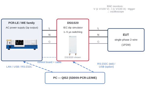
Figure 14. Single-phase test system (redrawn after Test circuit 1 of the DSI1020/DSI3020 Operation Manual): one PCR-LE/WE-family supply feeds the DSI1020, which delivers the dip-switched 1P2W voltage to the EUT. QIS2 on the controlling PC commands both instruments; BNC monitor outputs feed an oscilloscope for waveform verification.

Figure 15. Three-phase test system for the WEA2 family (redrawn after Test circuit 4 of the Operation Manual): a single multi-type PCR-LE2/WE2/WE2R/WEA2/WEA2R unit in 3P4W output feeds the DSI3020, which serves 1P2W, 1P3W, 3P3W, and 3P4W EUTs up to 400 V line voltage with both phase- and line-voltage dips.
Selecting the Right Model
| Typical EUT | Key sizing figures | Suggested configuration |
|---|---|---|
| Small appliance, ITE, lab instrument (≤10 A, 100–240 V, single-phase) | ≤10 A rms; inrush ≤40 A peak | PCR1000WEA (10 A L-range) or PCR2000WEA (20 A) — bench-top class |
| 16 A-class product at the -4-11 boundary (e.g., 230 V / 16 A) | 16 A rms; inrush to ~64 A peak; -4-11 requires up to 500 A generator capability or measured-inrush sizing | PCR3000WEA2 / PCR6000WEA2 (30/60 A L-range, 120/240 A peak); DSI pairing for certified switching edges |
| Three-phase industrial drive or power supply, 200 V class, >16 A/phase (-4-34) | Per-phase rating in three-phase mode (derated vs single-phase); recovery inrush at all three phases | PCR12000WEA2–PCR36000WEA2 multi-type (software-switchable 1φ/1φ3W/3φ); parallel operation above 36 kVA |
| 400/480 V-class line-to-line equipment | L-L voltage above the 320 V direct range | Multi-type WEA2 + OT03-PCR-WEA step-up transformer option |
| Regenerating / bidirectional EUT (drive with braking, inverter) | Reverse power flow into the source during test | PCR-WEA2R models — 100 % regeneration to the facility input, ≈85 % efficiency |
A Step-by-Step Test Workflow
- Classify the EUT: rated input current per phase (→ -4-11 or -4-34), phase configuration, and the class (2/3/X) and performance criteria assigned by the applicable product standard.
- Build the test matrix: levels × durations × onset angles × phase combinations (six series for three-phase with neutral). SD009 stores this as chained sequences.
- Run preliminary/margin tests first: reduced severities, then beyond-standard severities, to find the actual ride-through boundary and to catch criterion-D risks (fuse stress, transformer saturation) before the formal run.
- Run the compliance sequence: three events per point, ≥10 s intervals, EUT in its representative operating mode, monitoring input current and functional state throughout.
- Record and report: SD009’s txt/csv export captures every parameter; add the observed criterion per event and the generator-conformance evidence (or the DSI/accredited-lab pathway for the switching-edge requirement).
Compliance Boundaries — Stated Honestly
- Fully covered by PCR-WEA2 + SD009: voltage variations (abrupt drop, 1-cycle hold, 25/30-cycle ramp recovery); all dip/interruption levels, durations, phase angles, and three-phase combinations for development, characterization, and preliminary testing; the surrounding IEC 61000-4-x family; ride-through margin exploration beyond the standard levels.
- The 1–5 µs boundary: a PWM inverter’s output transition (40 µs typical in FAST mode) is faster than any real network event the EUT will meet, but slower than the 1–5 µs Table 4 requirement measured into the 100 Ω reference load. For strictly compliant dip/interruption switching edges — e.g., final certification where the test house measures generator conformance — Kikusui’s DSI1020/DSI3020 dip simulator supplies the certified edge (1–5 µs, 500 A peak, <5 % overshoot) under the same QIS2 software, or an accredited lab’s generator can be used for the final run. For EUTs above 75 A per phase under IEC 61000-4-34, the relaxed 50 µs limit brings direct testing with a high-performance programmable source into full-compliance territory.
- Inrush capability: the 4× peak-current rating (crest factor 4) covers EUT recovery inrush within each model’s envelope — e.g., a PCR36000WEA2 in single-phase L-range operation delivers up to 1,440 A peak on its output (360 A rms × 4). Read that as a per-phase figure in single-phase mode, and compare it with the standard’s inrush requirement on the same basis, because the requirement is itself per-phase: in three-phase and 1φ3W configurations the per-phase rms rating is lower than the single-phase rating, so take the applicable current from the model ratings before sizing. Edition 3’s measured-inrush provision then allows right-sizing the source to the EUT’s actual demand.

Figure 16. A chained dip/interruption profile of the kind SD009 executes automatically: each level applied as a series of three events with ≥10 s recovery intervals (compressed here for illustration), while the software logs the EUT response for the report.
Questions & Answers
About the Standards
Q. What changed in IEC 61000-4-11 Edition 3.0 (2020)? A. The test levels and classes carried over from Edition 2; Edition 3 formally defined rise/fall time (10–90 % points), stated the origin of dips and interruptions explicitly, clarified generator verification, and added pragmatic provisions such as using the EUT’s measured inrush to size the generator’s drive capability.
Q. What is the difference between IEC 61000-4-11 and IEC 61000-4-34? A. The phenomena, classes, and levels are the same. -4-11 applies at ≤16 A per phase; -4-34 above 16 A per phase, with three-phase application rules (individual line-to-neutral and line-to-line dips), generator drive capability scaled to the EUT, and a relaxed 50 µs switching-time allowance above 75 A per phase.
Q. Which equipment class do I test to — and who decides? A. The applicable generic or product standard decides, based on the intended installation environment: Class 2 for equipment connected at points of common coupling with the public network, Class 3 for in-plant industrial connection points (large drives, welders, frequently switched heavy loads nearby). If your product standard specifies Class X, the levels come from that committee’s table, not from -4-11 itself.
Q. What is the difference between the dip test and the voltage variation test? A. A dip is an abrupt rectangular event — abrupt drop, hold at the residual voltage, abrupt recovery. The (optional) voltage variation test is a shaped profile: abrupt decrease to 70 %, one cycle at the reduced level, then a gradual ramp back over 25/30 cycles — representing slow regulation events rather than faults. Some product standards require both.
Q. My equipment runs on DC or on 400 Hz — do these standards apply? A. No. DC-input dips and interruptions are covered by IEC 61000-4-29 (and ripple by -4-17), both included in SD009. Avionics 400 Hz and variable-frequency buses are covered by RTCA DO-160 Section 16 and MIL-STD-704 — see Kikusui’s companion white paper on avionics power quality testing.
Test Practice
Q. Do dips have to start at a zero crossing? A. Zero crossing is the baseline; product committees add angles from the preferred set 45°, 90°, 135°, 180°, 225°, 270°, 315° where the EUT physics warrants it (transformer saturation and rectifier conduction depend on the onset angle). The angle must be programmable and reported.
Q. Why three events with at least 10 s spacing? A. Three events give confidence that the behavior is repeatable rather than a one-off; the ≥10 s interval lets the EUT’s DC bus, PFC stage, and protection logic return to steady state so each event is applied to a defined initial condition.
Q. Can a dip test damage the EUT? A. It can — that is what performance criterion D records. The riskiest moments are recovery inrush (rectifier and fuse stress) and half-cycle 0 % dips on transformer-input products, where asymmetric flux can drive the core into saturation. Run preliminary tests at reduced severity first, and monitor input current during the campaign.
Q. What must the test report contain? A. The selected class and levels, dip durations, onset phase angles, phase combinations tested (for three-phase EUTs), the number of events and intervals, EUT operating mode, the performance criterion observed for every event, and evidence of generator conformance. SD009’s settings/results export (txt/csv) covers the parameter record automatically.
Equipment Selection
Q. How do I size the AC source for my EUT? A. Start from the EUT’s rated current per phase in the intended output range (L: 0–160 V, H: 0–320 V — H-range current ratings are half of L-range), check the three-phase/1φ3W derating on multi-type models, then verify inrush: the PCR-WEA2 delivers 4× rated current at crest factor 4, which must exceed the EUT’s recovery inrush. For 480 V-class line-to-line voltages, add the step-up transformer option.
Q. Where exactly is the full-compliance boundary for the PCR-WEA2? A. Everything except the 1–5 µs switching edge: levels, durations, angles, phase combinations, variations, and the surrounding -4-x family are covered. The Table 4 rise/fall requirement (1–5 µs into 100 Ω) exceeds any PWM inverter’s transition speed (40 µs typical FAST mode), so strictly conformant switching edges come from the DSI1020/DSI3020 dip simulator (1–5 µs, 500 A peak, 45°-step onset angles) under the same QIS2 software. Above 75 A per phase under -4-34, the 50 µs allowance closes this gap.
Q. Can the same setup run DC-input immunity tests? A. Yes — the PCR-WEA2 outputs DC to ±452 V, and SD009 includes IEC 61000-4-17 and -4-29 test types, so AC and DC ports of the same product are tested from one bench.
Conclusion
IEC 61000-4-11 and IEC 61000-4-34 look simple — drop the voltage, watch the EUT — but the details carry the compliance risk: class-correct levels and durations, three events at ≥10 s spacing, controlled onset angles, per-phase application on three-phase equipment, microsecond switching edges, and inrush drive capability. A test plan built on the PCR-WEA2 Series with SD009 software covers the full development and preliminary-compliance workflow — plus the neighboring IEC 61000-4-x tests — on one platform, with a clearly defined, honest path (dip-simulator pairing or accredited-lab final run) for the strict switching-edge requirement of formal certification. For configuration advice or a demonstration, contact Kikusui America at kikusuiamerica.com.