DC Withstand Voltage Testing
When AC Testing Falls Short — A Practical Guide to High-Capacitance and DC-Operated DUTs
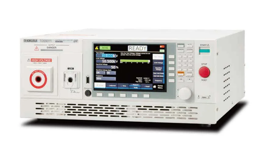
Kikusui TOS9311 — AC/DC Withstand Voltage Tester (Reference)
Published by Kikusui America, Inc. | Rev. 1.0 — April 2026
Subject: DC withstand voltage testing — methodology, parameter selection, and AC vs. DC test comparison
Executive Summary
For most consumer electronics connected to the AC mains, AC withstand voltage testing remains the standard. However, an increasing share of modern products — electric vehicles, energy storage systems, solar inverters, industrial transformers, and large electric motors — present test characteristics that fundamentally break the AC withstand methodology.
The root cause is internal capacitance. When a DUT has substantial parasitic or designed-in capacitance, AC testing produces two failure modes that put manufacturers at risk:
- The Capacitive-Current Avalanche: During AC testing of a high-capacitance DUT, reactive current can exceed true leakage current by 100× or more. The tester either trips on inrush, or — more dangerously — the operator raises the threshold to allow PASS, masking real insulation defects in the noise floor.
- The DC-Operated Blind Spot: EV battery packs, DC bus capacitors, and PV strings operate at DC. Their insulation systems are designed against DC stress, and the relevant safety standards (UL 2580, UL 1741, UL 1973) prescribe DC test methods. Testing them with AC is not equivalent — it leaves the actual operating-condition failure modes unverified.
DC withstand voltage testing solves both problems. Once the initial charging current settles, only true resistive leakage remains — enabling direct measurement of insulation quality without capacitive interference. This white paper provides design, QA, and compliance engineers with a practical methodology for executing DC withstand voltage tests, including parameter selection per North American standards, the AC-to-DC test voltage conversion, residual-charge handling, and a side-by-side AC/DC measurement comparison on the same DUT.
Safety Disclaimer
For qualified personnel only. DC withstand voltage testing involves hazardous voltages and stored charge. Always discharge the DUT through the tester’s built-in discharge circuit before disconnecting leads, and consult the applicable safety standards (UL, IEC, CSA, etc.) for your specific product category before conducting tests.
1. Purpose of DC Withstand Voltage Testing
Most electrical products — including home appliances — designed to connect to the commercial AC power grid undergo an AC withstand voltage test prior to shipment to verify their safety.
However, since AC withstand voltage testing involves applying an AC voltage to the Device Under Test (DUT), issues arise when testing DUTs with high capacitance — such as electric motors, transformers, solar panels, and cables. The high capacitance causes a significant reactive current to flow, making it difficult to accurately measure the leakage current.
Consequently, for DUTs exhibiting such high capacitance, as well as for DUTs intended for DC operation (e.g., electric vehicles and batteries), a DC withstand voltage test is performed instead.
Reference Tester — Kikusui TOS9311: This withstand voltage tester is capable of performing withstand voltage tests by applying a maximum DC voltage of 10 kV to the test specimen.
2. Navigating the Regulatory Landscape
DC withstand voltage testing is a specialized requirement integrated into both international (IEC) and North American (UL/CSA) safety standards. While IEC 62368-1 establishes the foundational “Hazard-Based” logic for insulation safety, specific North American standards prescribe DC methods to address parasitic capacitance and system-specific stresses.
| Standard | Scope | DC Provision |
|---|---|---|
| IEC 62368-1 | Global foundation — audio, video, and ICT equipment | Permits DC testing for high-capacitance equipment using the peak-equivalent formula, validating insulation integrity without reactive-current interference |
| UL 5085-3 / CSA C22.2 No. 66.3 | Low-voltage transformers (primary case study of this paper) | Provides clear DC equivalents for AC test voltages for transformers used in ICT and industrial applications |
| UL 2580 / SAE J2929 | Batteries for electric vehicles | Withstand voltage testing on battery enclosures and bus structures performed at DC voltages corresponding to operating-voltage stress |
| UL 1973 | Batteries for stationary, vehicle auxiliary power, and light electric rail applications | Specifies withstand voltage testing requirements for battery management systems and enclosures |
| UL 61010-1 / CSA C22.2 No. 61010-1 | Test, measurement, and laboratory equipment | DC withstand voltage testing permitted as an alternative to AC for high-capacitance equipment |
| UL 1741 / IEEE 1547 | Distributed Energy Resources — PV inverters and battery storage systems | DC testing is the standard for validating the DC bus and interconnection structures, where AC testing is often impractical due to internal filtering components |
When to Choose DC Over AC Testing
A common question during test design is whether to use AC or DC voltage. The decision hinges on three factors: the DUT’s capacitance characteristics, its operating-voltage type, and the requirements of the governing standard.
| Decision Factor | Favors AC Testing | Favors DC Testing |
|---|---|---|
| DUT capacitance | Low total parasitic capacitance (sub-nF to low-nF range) | Substantial capacitance (motors, transformers, long cables, EV battery packs, PV strings) |
| Operating-voltage type | DUT operates from AC mains | DUT is intended for DC operation |
| Governing standard | Standard prescribes AC | Standard prescribes DC |
| Practical trade-off | AC stress in both polarities closely mimics real-world operating conditions | Clean leakage measurement after the initial charging transient, but the DUT must be safely and completely discharged after the test |
3. Determining Test Parameters
To conduct a DC withstand voltage test, it is necessary to first define the test parameters. The primary test parameters include the following items:
- 3.1 Test voltage
- 3.2 Test points (e.g., primary-to-secondary, primary-to-core)
- 3.3 Test duration
- 3.4 Acceptance criteria (current value)
3.1 Test Voltage
For demonstration purposes, we will use a transformer as the Device Under Test (DUT). In the global market, IEC 62368-1 serves as the hazard-based safety standard for audio, video, and ICT equipment. (This standard focuses on energy sources and replaces the older IEC 60065 and IEC 60950-1 frameworks.)
The test voltage requirements are determined by the overvoltage category and working voltage. For equipment rated at 120 VAC, the required test voltage is 1,500 VAC (2,121 VDC) for basic insulation, and 3,000 VAC (4,242 VDC) for reinforced or double insulation.
| Insulation Class | AC Test Voltage | DC Equivalent |
|---|---|---|
| Basic | 1,500 VAC | 2,121 VDC |
| Reinforced / Double | 3,000 VAC | 4,242 VDC |
AC-to-DC Test Voltage Conversion: When the standard specifies an AC test voltage but DC testing is preferred (or required) for the DUT, the DC equivalent is conventionally calculated as: V(DC) = V(AC, rms) × √2 ≈ V(AC, rms) × 1.414. This produces a DC voltage with the same peak value as the original AC test voltage. Always verify that the governing standard accepts this substitution.
3.2 Test Points
Typical test points for a transformer include the primary winding (AC power source), the secondary winding, and the iron core. (The specific test points vary depending on the object under test.)
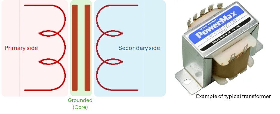
Figure 1. Schematic of a typical transformer (left) and example of a small power transformer (right). The left side represents the primary winding, the right represents the secondary winding, and the central section represents the grounded iron core.
During a withstand voltage test, voltage is applied between the primary and secondary windings, as well as between the primary/secondary windings and the iron core, to verify that no electrical discharge occurs.
3.3 Test Duration
The duration of a withstand voltage test varies depending on the specific objective of the examination.
During the equipment development and evaluation phases — specifically in Type Testing (or certification testing) — the test voltage is applied to the DUT for a duration of 60 seconds to monitor the current flowing through it. In contrast, during Mass Production Testing (or manufacturing/routine testing), the test duration may be shortened to as little as one second, based on thorough verification and established protocols.
This disparity in test duration stems from the differing verification objectives associated with each stage of testing. The purpose of Type Testing is to validate the soundness of the insulation design and the suitability of individual components. Consequently, a high voltage is applied for a substantial period — 60 seconds — to detect any potential insulation breakdown or degradation that may occur within the insulating materials or components.
Conversely, the primary objective of Mass Production Testing is to identify manufacturing defects, such as wiring errors, the presence of foreign objects, or damaged wiring. Therefore, taking into account factors such as economic efficiency and the specific scope of the evaluation, a one-second withstand voltage test is sometimes deemed sufficient to assess withstand voltage performance at this stage.
3.4 Acceptance Criteria (Current Value)
In many standards, the pass/fail criterion for a withstand voltage test is simply that no dielectric breakdown occurs. In other words, as a general rule, the pass/fail criterion is the absence of dielectric breakdown, regardless of the magnitude of the current flow.
In AC withstand voltage testing, current may flow through the DUT — even if the unit itself is free of defects — due to the presence of capacitors within filter circuits or parasitic capacitance. However, in DC withstand voltage testing, no steady-state current flows through capacitance once the initial charging transient subsides, thereby enabling the measurement of pure leakage current. This is the principal practical advantage of DC testing for high-capacitance DUTs.
The Hidden Cost of Forcing AC on a High-Capacitance DUT
Consider an industrial transformer with 50 nF of inter-winding capacitance, AC-tested at 5,000 Vrms / 60 Hz. The reactive (capacitive) current alone would be approximately 94 mA — far exceeding any realistic leakage threshold and overwhelming any defect-related current. This forces engineering teams into a no-win choice: either set thresholds in the hundreds of mA range (masking genuine insulation defects), or abandon withstand voltage testing of these critical safety boundaries entirely. Both outcomes leave real failure modes unverified, opening the door to field failures and certification challenges. DC testing eliminates this dilemma. After the initial charging current settles, only true leakage flows. The same transformer, DC-tested, may read just sub-microamp leakage — a clean signal that genuinely reflects insulation health.
4. Actual Testing Procedures
4.1 Determination of Test Sections
The specific sections subject to testing are determined based on the requirements of the relevant standards. For this example, we assume a typical transformer consisting of a primary winding, a secondary winding, and an iron core.
For this experiment, we will use a transformer found in the office. This transformer is designed to generate an output voltage of 48 VAC from its secondary winding when the input voltage to the primary winding is 120 VAC.
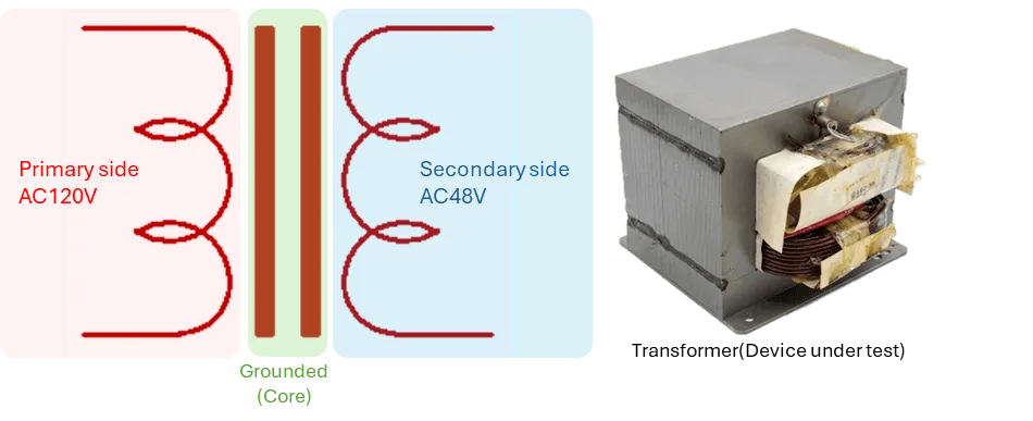
Figure 2. Schematic of the microwave-oven transformer (left) and the actual unit (right). Primary side rated 132 VAC, secondary side rated 2,500 VAC, iron core grounded.
4.2 Verification of Test Voltage and Test Points
Let’s conduct testing in accordance with the aforementioned IEC 62368-1 standard.
Determination Steps
- Step 1: Transient Voltage — Based on the mains supply. For a 120V system (Overvoltage Category II), the transient voltage is 1,500V.
- Step 2: Working Voltage — The continuous stress voltage. In this case, the baseline is the primary input of 120 VAC.
- Step 3: Insulation Classification — Basic: Primary to Ground (Chassis). Reinforced: Primary to Secondary (User-accessible side).
Required Test Voltages
- For Reinforced Insulation (typically between the Primary and Secondary windings), the standard requires a test voltage of 3,000 VAC (or 4,242 VDC).
- For Basic Insulation (typically between the Primary winding and the Grounded chassis), the requirement is halved to 1,500 VAC (or 2,121 VDC).
For this session, focusing on tests of the primary and secondary windings, we will conduct the testing under conditions based on reinforced insulation.
4.3 Pre-Test Safety and Setup Checklist
Before applying high voltage, ensure the following steps are verified to protect both the operator and the validity of the test. DC testing introduces an additional consideration — stored charge — that AC testing does not, so discharge protocol items appear in this checklist:
- ☐ Environment: The test station is equipped with an insulated mat, and unauthorized personnel are kept away via physical barriers or warning lights.
- ☐ Grounding: The withstand voltage tester is properly grounded to earth, and the DUT’s designated ground reference is securely connected.
- ☐ DUT Preparation: All relevant power switches on the Device Under Test are in the “ON” position so the internal circuits are fully exposed to the test voltage.
- ☐ Terminal Shorting: Where applicable, terminals on the same winding or bus are shorted together to ensure uniform voltage distribution and prevent damage to internal components.
- ☐ Discharge Path Verified: The tester’s built-in discharge circuit is enabled, and a manual discharge tool (grounding stick) is within reach as a backup.
- ☐ Parameter Verification: Test voltage, ramp time, hold time, and current threshold are programmed and double-checked against the governing standard.
4.4 Connection of the Withstand Voltage Tester and the DUT
The basic connection configuration is shown in the photograph below.
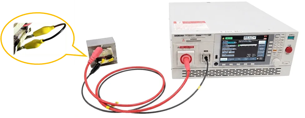
Figure 3. Basic connection configuration between the microwave-oven transformer DUT (left) and the TOS9311 withstand voltage tester (right). The inset highlights how the alligator clips are attached to the primary leads.
Key points regarding the connection and testing environment include:
- If the DUT is equipped with a power switch, ensure it is set to the “ON” position.
- If the section under test contains multiple terminals, short-circuit them. (For tests conducted between the primary circuit and Ground, short-circuit the Live and Neutral terminals of the primary circuit.)
- Place the DUT on a sturdy, non-conductive surface.
- Enclose the surrounding area with a fence or similar barrier to prevent anyone other than the operator from inadvertently touching the withstand voltage tester or the DUT.
4.5 Safety Tester Configuration
Set the test voltage, current threshold, and test duration.
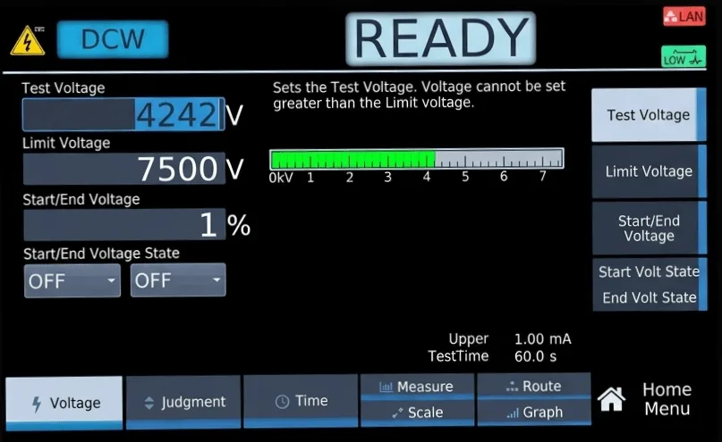
Figure 4a. Voltage Setting Screen.
- Voltage Setting: DC 7,070 V
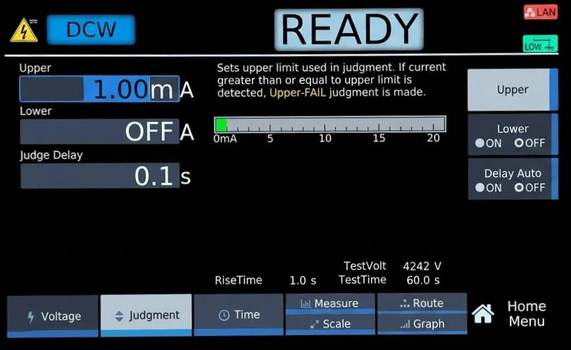
Figure 4b. Judgment Settings Screen.
- Upper Threshold: 1 mA
For DC testing of a small transformer with negligible parasitic capacitance, a sub-mA threshold is appropriate. Larger DUTs require thresholds calibrated to expected leakage.
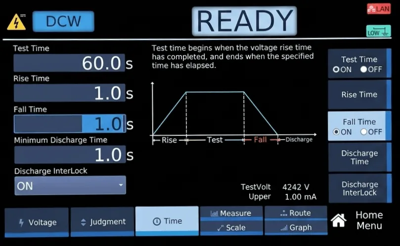
Figure 4c. Time Settings Screen.
- Test Duration: 60 seconds
- Voltage Rise Time: 1 second
- Voltage Fall Time: 1 second
The voltage rise and fall times help prevent damage to the DUT and reduce the likelihood of false judgments. The fall time is also part of the controlled discharge sequence.
4.6 Conducting a Withstand Voltage Test
Press and hold the START button to begin the test. The voltage and current applied to the DUT are displayed on the screen. If a fault occurs and the measured current falls outside the specified range, the test will automatically stop.
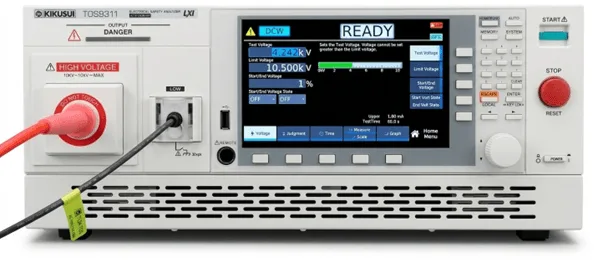
Figure 5a. Standby State — “READY” indicates that the test can be started by pressing the START button.
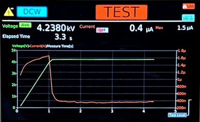
Figure 5b. Test in Progress — voltage rises along the configured ramp; the current trace shows the initial charging transient settling toward the steady-state leakage value.
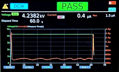
Figure 5c. PASS — The 60-second hold completed with leakage of 0.4 μA throughout, well below the 1 mA threshold.
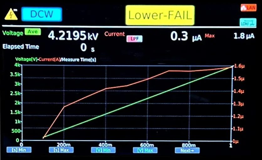
Figure 5d. Lower-FAIL — Test stopped because the test current dropped below the lower limit (if a lower threshold is enabled, often used to detect disconnected leads).
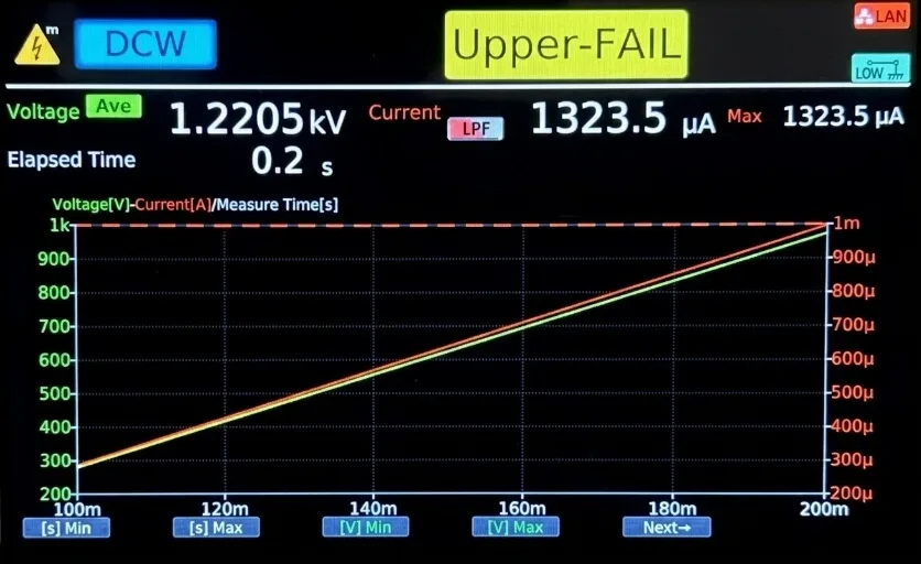
Figure 5e. Upper-FAIL — Test stopped because the test current exceeded the upper limit (1 mA in this configuration).
5. Precautions During Testing
The following points require attention during the DC withstand voltage test. The first four are common to AC and DC testing; the fifth is specific to DC and reflects the principal residual hazard of the method.
- Do not touch the DUT or cables while testing is in progress.
- Ensure that the DUT and cables are securely connected.
- Display a warning indicating that a withstand voltage test is being conducted to prevent bystanders from touching the DUT or cables.
- If there are three or more test points, exercise caution, as residual charge may accumulate in areas other than the specific sections currently under test.
- While the TOS9300 series features a function to discharge the charge accumulated in the DUT upon the completion of a test, extreme caution regarding residual charge is still required. For high-capacitance DUTs, always verify with an external high-voltage probe that the voltage has decayed to a safe value before disconnecting leads.
6. Side-by-Side: DC vs. AC Test Results on the Same DUT
To make the practical difference between DC and AC withstand voltage testing concrete, the same microwave-oven transformer was tested with both methods. The results below are taken directly from the TOS9300-series instrument display.
The test voltage for the DC withstand voltage test was 4,242 V DC, while the test voltage for the AC withstand voltage test was 3,000 V AC at a frequency of 60 Hz. (These are equivalent in peak voltage stress.)
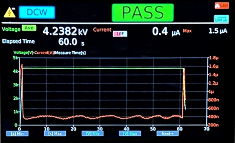
Figure 6a. DC Withstand Voltage Test — Test Result: 0.4 μA. In practical terms, since 0.4 μA represents the lower measurement limit of the TOS9300 series, the transformer exhibits virtually no leakage current. The offset cancellation function compensates for instrument errors and fixture leakage.
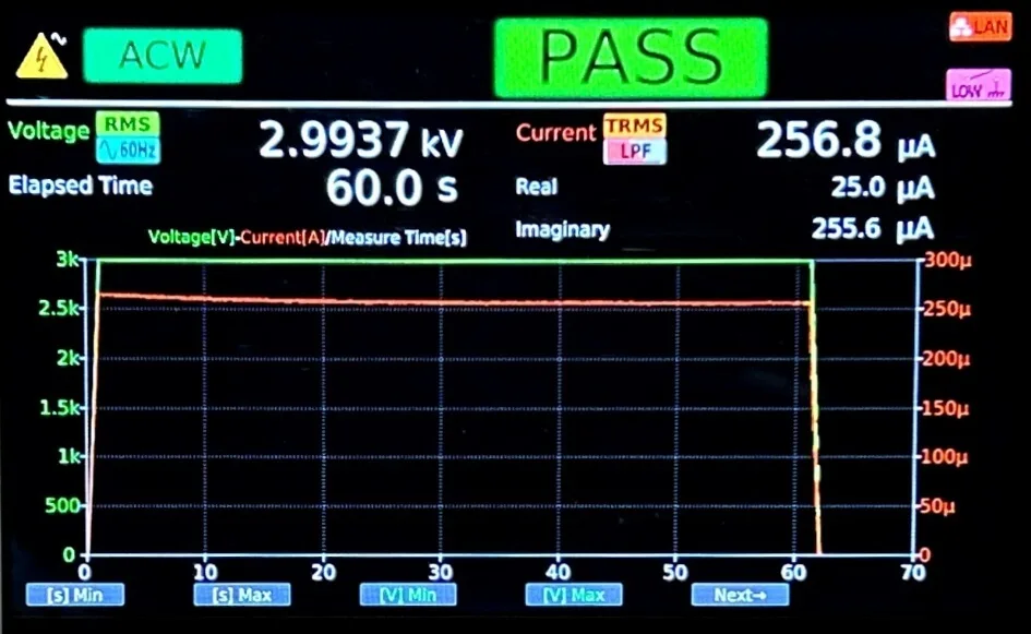
Figure 6b. AC Withstand Voltage Test — Test Result: 256.8 μA. The TOS9311 display indicated an “Imaginary” component of 255.6 μA, confirming that almost the entire current is reactive — attributable to parasitic capacitance between the windings, not to insulation leakage.
| Parameter | DC Withstand Test | AC Withstand Test |
|---|---|---|
| Applied Voltage | 4,242 V DC | 3,000 Vrms AC / 60 Hz |
| Measured Current | 0.4 μA (instrument lower limit) | 256.8 μA total |
| Reactive (Imaginary) Component | Not applicable | 255.6 μA (99.5% of total current) |
| Interpretation | Virtually no leakage current — a clean signal of insulation health | Reading dominated by parasitic-capacitance reactive current; conveys no information about insulation health |
As illustrated here, the results obtained from a DUT test can differ significantly depending on whether DC or AC voltage is applied. The same transformer reads 0.4 μA under DC and 256.8 μA under AC — a roughly thousandfold difference, with the AC reading dominated by reactive (capacitive) current that conveys no information about insulation health.
In conducting withstand voltage tests, it is crucial to carefully analyze the DUT’s characteristics and insulation structure to identify potential failure modes, thereby enabling the establishment of appropriate testing methods and acceptance thresholds.
7. Troubleshooting & FAQ
Common questions about DC withstand voltage testing, AC-to-DC conversion, and residual-charge handling.
Q1. When should I choose DC over AC for hipot testing?
Three triggers should push you toward DC: (1) the DUT has substantial designed-in or parasitic capacitance (motors, transformers above a few VA, long cables, EV battery packs, PV strings); (2) the DUT operates from DC, so its insulation system is designed against DC stress; (3) the governing standard explicitly prescribes or permits DC. If none of these apply and the standard accepts AC, AC testing usually remains the simpler choice.
Q2. How do I convert an AC test voltage spec to its DC equivalent?
The conventional conversion is V(DC) = V(AC, rms) × √2 ≈ V(AC, rms) × 1.414, producing a DC voltage with the same peak value as the AC waveform. For example, 1,000 Vrms AC corresponds to approximately 1,414 V DC. Always verify the substitution against the governing standard — some standards (e.g., UL 5085) explicitly tabulate both AC and DC test voltages, while others mandate one or the other.
Q3. Why does my DC measurement drift during the 60-second hold?
Real insulating materials exhibit dielectric absorption — a slow polarization process that produces a decaying current over several seconds to minutes after voltage application. This is normal and is the basis of the Polarization Index (PI) test used in motor diagnostics. For pass/fail purposes, read the steady-state value at the end of the hold time, not during the initial settling period. The Kikusui TOS9300 series’s graphing function makes the settling behavior easy to inspect.
Q4. What discharge protocol should I follow for high-capacitance DUTs?
Rely on the tester’s built-in discharge first (the TOS9300 automatically engages an internal resistor), then for DUTs above ~10 nF wait until the displayed residual voltage is safe, and finally verify zero potential with a properly rated grounding stick before handling — never assume safety based on time alone.
Conclusion & Key Takeaways
Choosing between AC and DC withstand voltage testing is not a stylistic preference — it is a technical decision driven by the DUT’s capacitance, its operating-voltage type, and the governing standard. To ensure your withstand tests actually verify insulation health (rather than measuring capacitive noise), keep these takeaways in mind:
- Match Test Type to DUT Characteristics — Use AC for low-capacitance, AC-mains-connected products. Use DC for high-capacitance products (motors, transformers, batteries, PV, long cables) and for any product whose insulation is designed against DC stress in service.
- Convert Voltage Specifications Carefully — When substituting DC for an AC-specified test, V(DC) = V(AC, rms) × √2. Always confirm the substitution is permitted by the governing standard before deployment.
- Treat Discharge as a First-Class Test Step — DC testing leaves stored charge on capacitive DUTs. Configure ramp-down, rely on the tester’s discharge circuit, verify residual voltage with an external probe, and treat the discharge protocol as a non-negotiable part of every test cycle.
Why Kikusui?
Since 1949, Kikusui Electronics Corporation has been a global leader in electronic test and measurement instruments, renowned for uncompromised Japanese manufacturing quality and reliability.
Operating out of Torrance, California, Kikusui America, Inc. provides the North American market with direct access to specialized application engineers, rapid local support, and deep expertise in electrical safety testing automation — including the high-capacitance and DC-operated DUT scenarios where AC testing falls short.
Our Safety Tester Lineup for DC Applications
| Series | Description |
|---|---|
| TOS9300 Series — Flagship multi-function safety analyzer | Combines AC/DC Withstand Voltage, Insulation Resistance, Ground Bond, and Leakage Current testing in a single unit. The DC withstand mode delivers up to 10 kV with sub-microamp current resolution, an automatic discharge circuit, offset cancellation for fixture compensation, and a graphing display that makes dielectric absorption and leakage settling visible at a glance. |
| TOS5400 Series — Next-generation production standard | The successor to the industry-standard TOS5300 series. Designed with PWM amplifier technology for highly stable, low-distortion output independent of AC power line fluctuations — enabling consistent, repeatable test conditions on high-speed mass production lines testing both AC and DC dielectric strength. |
Ready to Optimize Your Testing Process?
If your product line includes EV components, energy storage systems, large transformers or motors, solar PV equipment, or any high-capacitance DUT, your current AC-only test process may be leaving real failure modes unverified. Our Torrance-based application engineers can help you evaluate where DC testing is required, where it is preferred, and how to integrate it into your existing production flow.
- → Request a Free Application Consultation — Have our engineers review your specific DUT characteristics and standards to recommend AC, DC, or a combined test approach.
- → Request a Demo Unit — Test-drive the TOS9300 or TOS5400 series on your own production floor with your actual DUTs.
- → Connect with Our Team — Discuss automation options for multi-point testing, scanners, and full production-line integration of AC and DC dielectric verification.