


AC Withstand Voltage Testing
A Practical Guide to Minimizing False Fails and Ensuring Compliance
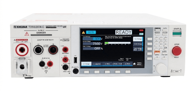
Kikusui TOS9303LC — AC/DC Withstand Voltage Tester (Reference)
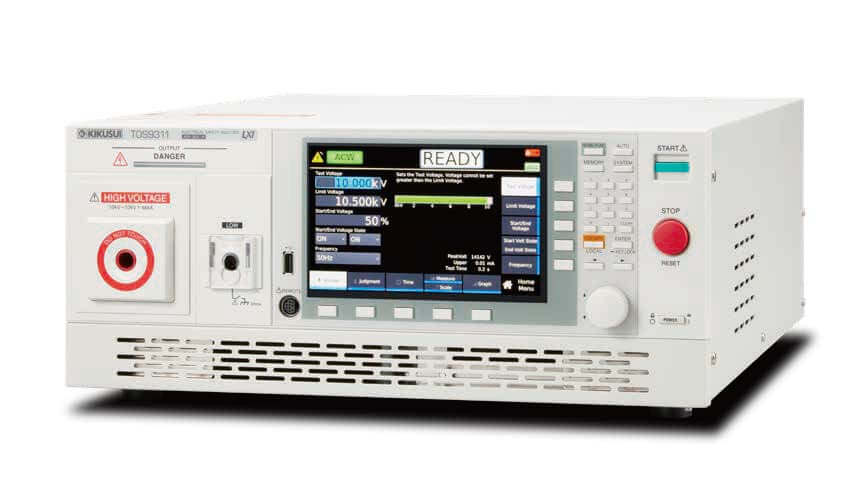
Kikusui TOS9311 — AC/DC Withstand Voltage Tester (Reference)
Published by Kikusui America, Inc. | Rev. 1.0 — April 2026
Subject: AC withstand voltage testing — methodology, parameters, and capacitive-current handling
Executive Summary
Compliance with electrical safety standards is not merely a box to check before shipment; it is a critical safeguard for your brand, your bottom line, and your end-users. In AC withstand voltage (hipot) testing, setting the correct pass/fail thresholds is often complicated by the presence of capacitive current generated by internal filter circuits (such as Y-capacitors).
Failing to properly account for this capacitive current leads to two severe business risks:
- False Fails (Underestimating Current): Good products are repeatedly rejected on the production line, leading to wasted technician hours for manual debugging, reduced manufacturing yield, and supply chain bottlenecks.
- False Passes (Overestimating Current): To avoid production delays, limits are sometimes set dangerously high. This masks true insulation defects, allowing hazardous products into the market and dramatically increasing the risk of field failures, expensive product recalls, and the loss of NRTL (e.g., UL, CSA) certifications.
This white paper provides design, QA, and compliance engineers with a practical methodology for executing AC withstand voltage tests. By understanding how to accurately calculate anticipated currents and configure precise upper and lower test limits, manufacturers can optimize production throughput while guaranteeing zero-defect safety compliance.
Safety Disclaimer
For qualified personnel only. High voltage testing presents inherent risks. Always consult the applicable safety standards (UL, IEC, CSA, etc.) for your specific product category before conducting tests.
1. Purpose of Withstand Voltage Testing
Many electronic devices operate at voltages that are potentially hazardous to humans. For instance, household appliances such as refrigerators and washing machines draw 120 V AC power from wall outlets for internal use.
Withstand voltage testing is conducted to ensure that users of these devices are not exposed to electric shock resulting from manufacturing defects or internal malfunctions. All devices handling hazardous voltages must undergo withstand voltage testing to verify safety before shipment.
Reference Tester — Kikusui TOS9311: This withstand voltage tester is capable of performing withstand voltage tests by applying a maximum AC voltage of 10 kV to the test specimen.
2. Navigating the North American Regulatory Landscape
Electrical products destined for the North American market must comply with stringent safety standards enforced by Nationally Recognized Testing Laboratories (NRTLs) such as UL and CSA. Common standards dictating withstand voltage test parameters include:
| Standard | Scope |
|---|---|
| UL 62368-1 / CSA C22.2 No. 62368-1 | The hazard-based standard for Audio/Video and Information/Communication Technology equipment |
| UL 61010-1 / CSA C22.2 No. 61010-1 | Safety requirements for electrical equipment used in testing, measurement, control, and laboratory settings |
| ANSI/AAMI ES60601-1 | Strict safety guidelines for medical electrical equipment, where leakage current limits are extraordinarily tight to protect patients |
| UL 60335-1 | Safety of household and similar electrical appliances — referenced throughout this paper as the worked example |
Furthermore, ensuring compliant equipment design directly supports workplace safety initiatives governed by OSHA 1910 Subpart S.
AC vs. DC Withstand Voltage Testing
A common question during test design is whether to use AC or DC voltage.
| Method | Characteristics |
|---|---|
| AC Testing | Preferred because it stresses the insulation in both polarities, closely mimicking the real-world stresses the AC mains will place on the device. However, AC testing inherently causes reactive (capacitive) current to flow continuously through Y-capacitors, which must be mathematically accounted for when setting fail limits. |
| DC Testing | Once the initial charging current subsides, only true resistive leakage current remains. This makes it easier to detect minute insulation flaws. However, DC testing requires the DUT to be safely and completely discharged after the test, adding time to the production cycle. |
3. Determining Test Parameters
To conduct a withstand voltage test, it is necessary to first define the test parameters. The primary test parameters include the following items:
- 3.1 Test voltage
- 3.2 Test points (e.g., primary-to-secondary, primary-to-enclosure)
- 3.3 Test duration
- 3.4 Acceptance criteria (current value)
3.1 Test Voltage
For example, under UL 60335-1 (applicable to household appliances in the United States), equipment with a mains voltage of up to 150 Vrms is tested at 1000 Vrms for basic insulation and 1500 Vrms for reinforced or double insulation. Test voltage levels may vary depending on the applicable safety standard (e.g., UL, IEC, or JIS).
| Insulation Class | Test Voltage (UL 60335-1, ≤150 Vrms mains) |
|---|---|
| Basic | 1000 Vrms |
| Reinforced / Double | 1500 Vrms |
Basic insulation is applied to parts where a failure of the insulation layer itself would not result in a direct connection between the power supply system and the human body. Examples of this include the insulation between a primary-side circuit and a grounded metal chassis.
Double or reinforced insulation is applied to parts where a failure in the insulation structure could potentially result in a direct connection between the power supply system and the human body. Examples of this include the insulation between the primary and secondary sides (such as the USB port) of a mobile phone charger.
Depending on the standard, the test voltage may be determined by taking into account transient overvoltages caused by factors such as lightning.
3.2 Test Points
Typical test locations include the primary side (AC mains), the secondary side (accessible parts), and the grounded enclosure. (The specific test locations vary depending on the test specimen.)
For example, if we consider a charger with a metal enclosure, the schematic diagram would look something like this. The left side represents the primary side, the right side represents the secondary side, and the outer shell represents the enclosure.
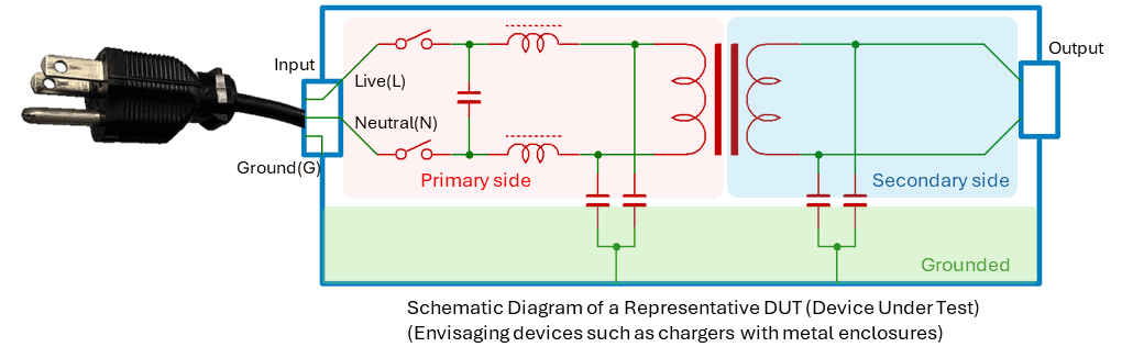
Figure 1. Schematic Diagram of a Representative DUT (Device Under Test). Envisaging devices such as chargers with metal enclosures.
In the withstand voltage test, a voltage is applied between the primary and secondary sides, as well as between the primary side and the enclosure, to verify that no discharge occurs.
3.3 Test Duration
The duration of a withstand voltage test varies depending on the specific objective of the test.
During Type Testing (Certification) — conducted during the development and evaluation phases of equipment — the test voltage is applied for 60 seconds to monitor the current flowing through the Device Under Test (DUT). In contrast, for Mass Production Testing (Production / Routine Testing), the test duration is frequently shortened to just one second.
The reason for this difference in duration lies in the distinct verification objectives associated with each testing phase. The purpose of Type Testing is to validate the insulation design and the suitability of individual components; consequently, a high voltage is applied for a full 60 seconds to detect any potential breakdown or degradation of the insulating materials or components.
In contrast, mass production testing primarily aims to detect manufacturing defects such as wiring errors, foreign objects, or damaged wiring. Therefore, taking into account both economic efficiency and the specific scope of the evaluation, a one-second withstand voltage test is deemed acceptable for this phase.
3.4 Acceptance Criteria (Current Value)
In many standards, the pass/fail criterion for a withstand voltage test is simply the absence of dielectric breakdown. In other words, in principle, the pass/fail criterion is the absence of dielectric breakdown, regardless of the current magnitude. However, relying solely on this criterion makes it difficult to clearly determine the pass/fail status of the test.
Therefore, it is standard practice to configure the withstand voltage tester with a specific current threshold that triggers a test failure. In AC withstand voltage testing, current flows through capacitors present within the filter circuitry; consequently, the failure threshold is set to a value equal to this current magnitude plus an added safety margin. The current flowing through the capacitors is calculated based on the test voltage, the test frequency, and the total capacitance of the components within the voltage application circuit.
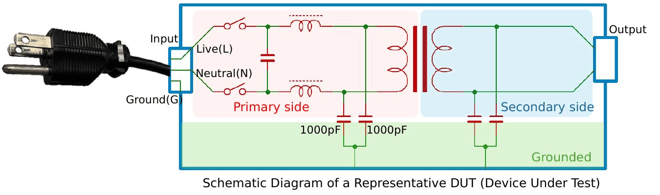
Figure 2. Schematic with 1000 pF Y-capacitors on the primary side (Live and Neutral).
For example, if there are 1000 pF Y capacitors in both the Live and Neutral circuits on the primary side, the current flowing through the capacitors when a voltage withstand test is performed between the primary side and the chassis will be:
I(Capacitor) = V_test / Z_c = 1000 V / [ 1 / (2π × 60 Hz × 2000 pF) ] = 1000 V / 1.33 MΩ = 0.75 mA
The calculated value is 0.75 mA. Since capacitor values have tolerance, it is advisable to include a safety margin. In this case, the test current threshold is set to approximately 1 mA.
During the dielectric withstand testing phase of an evaluation, current may occasionally flow through sections possessing capacitance that was not anticipated in the design. In the example illustrated in the figure, this would include the capacitance between the primary and secondary windings of the transformer.
Particularly during the initial dielectric withstand test, it is essential to conduct the procedure while monitoring to ensure that there is no significant discrepancy between the current predicted for the test and the current actually flowing through the circuit.
The Hidden Cost of “Guessing” Test Limits
Imagine a production line manufacturing 10,000 power supplies per month. If the upper current limit is set arbitrarily without calculating the total 22,000 pF line-to-ground capacitance, natural component tolerances might trigger a 2% “False Fail” rate. That equates to 200 perfectly safe units sent to the rework station every month. At an estimated $50/hour for engineering diagnosis and rework, this easily costs the manufacturer tens of thousands of dollars annually in wasted labor alone. Conversely, a “False Pass” that results in a shock hazard can trigger a CPSC recall — industry estimates suggest direct costs often exceed $1 million, not including catastrophic damage to brand reputation.
4. Actual Testing Procedures
4.1 Determination of Test Sections
The specific sections to be tested are determined based on the requirements of the relevant standards. For this example, we will use an electrical product featuring a primary circuit, a secondary circuit, and a metal enclosure.
For the secondary circuit, the determining factor is whether it is accessible to the user. As for the enclosure, the key factor determining the necessity of testing is the material from which it is constructed.
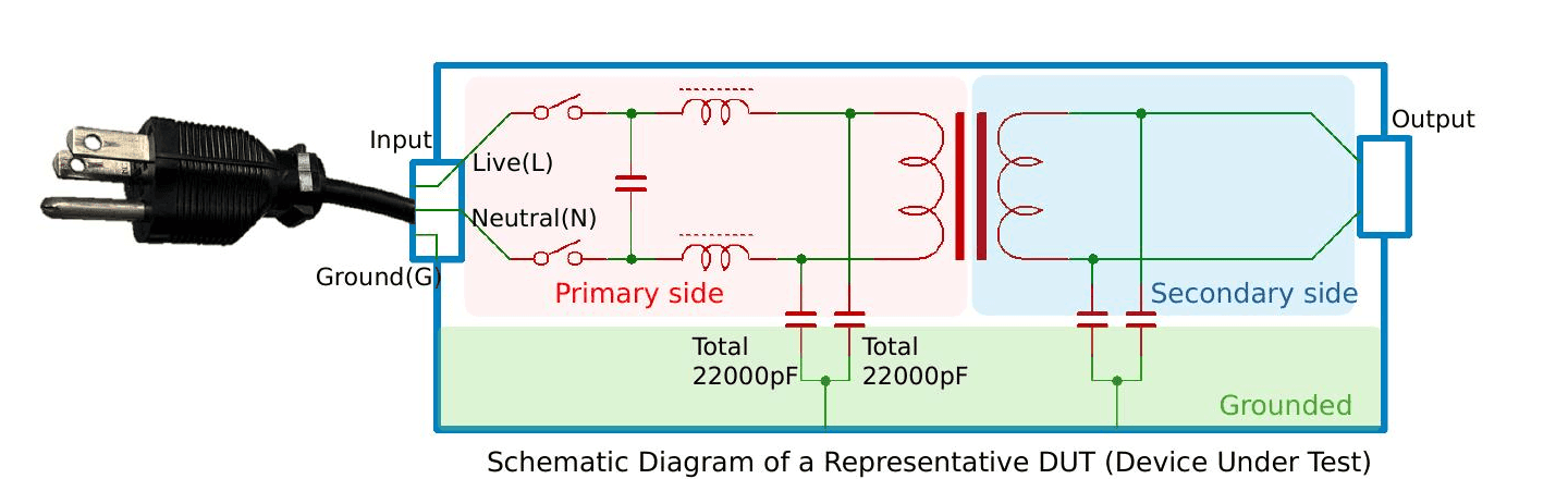
Figure 3. Schematic with total capacitance of 22000 pF (44000 pF total across Live-Ground and Neutral-Ground).
4.2 Verification of Test Voltage and Test Points
As previously noted, basic insulation is required between the primary circuit and the metal enclosure; therefore, when complying with UL 60335-1, a test is conducted by applying 1000 Vrms between the primary circuit and the metal enclosure.
When testing between the primary and secondary circuits — where reinforced or double insulation is required — a test is conducted by applying 1500 Vrms.
4.3 Calculation of Test Termination Conditions (Current Threshold)
The current flowing through the test site is calculated from the capacitance of the test site, the test voltage, and the frequency. Since capacitors are used in the filter circuit, their capacitances are added together. In this test subject (PWR1201ML), 22000 pF (44000 pF total) is connected between Live-Ground and Neutral-Ground.
Therefore, the expected test current is:
I(Primary–Ground) = V_test / Z_c = 1000 V / [ 1 / (2π × 60 Hz × 44000 pF) ] = 1000 V / 60.3 kΩ = 16.6 mA
Setting a threshold value that is too close to the calculated value risks triggering false positives due to variations such as component tolerances; therefore, we will set the threshold to a round figure of 20 mA. In the actual test, the anticipated current for each specific test site is calculated to determine the current threshold at which a failure is declared during testing.
4.4 Pre-Test Safety and Setup Checklist
Before applying high voltage, ensure the following steps are verified to protect both the operator and the validity of the test:
- Environment: The test station is equipped with an insulated mat, and unauthorized personnel are kept away via physical barriers or warning lights.
- Grounding: The withstand voltage tester is properly grounded to earth.
- DUT Preparation: All relevant power switches on the Device Under Test are in the “ON” position so the internal circuits are fully exposed to the test voltage.
- Terminal Shorting: Line and Neutral terminals on the primary side are shorted together to prevent high voltage from damaging internal components across the primary circuit.
- Parameter Verification: Test voltage, frequency, ramp time, and calculated Upper/Lower current limits are programmed and double-checked.
4.5 Connection of the Withstand Voltage Tester and the DUT
The basic connection configuration is shown in the photograph below.
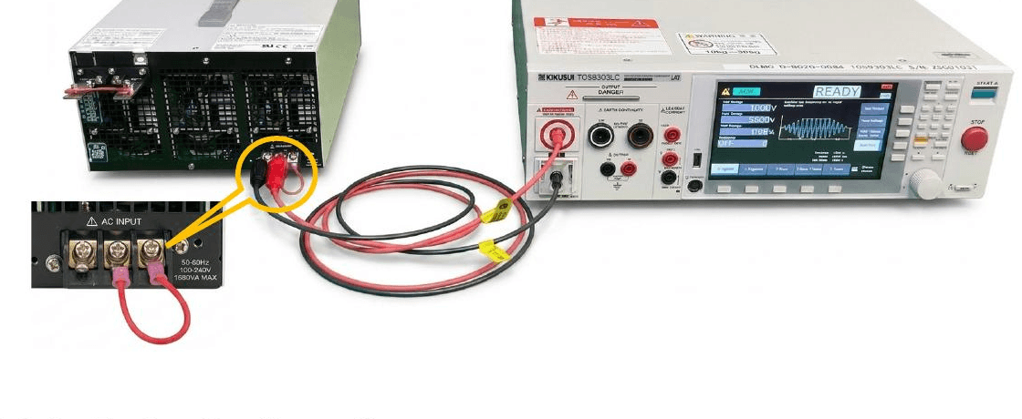
Figure 4. Basic Connection Configuration between the DUT (left) and the TOS9303LC withstand voltage tester (right).
Key points regarding the connection and testing environment include:
- If the DUT is equipped with a power switch, ensure it is set to the “ON” position.
- If the section under test contains multiple terminals, short-circuit them. (For tests conducted between the primary circuit and Ground, short-circuit the Live and Neutral terminals of the primary circuit.)
- Place the DUT on a sturdy, non-conductive surface.
- Enclose the surrounding area with a fence or similar barrier to prevent anyone other than the operator from inadvertently touching the withstand voltage tester or the DUT.
4.6 Safety Tester Configuration
Set the test voltage, test frequency, current threshold, and test duration.

Figure 5a. Voltage Setting Screen.
- Voltage Setting: AC 1000 V
- Test Frequency: Set to 60 Hz
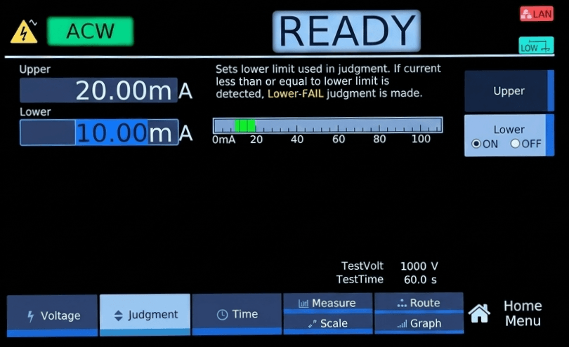
Figure 5b. Judgment Settings Screen.
- Upper Threshold: 20 mA
- Lower Threshold: 10 mA
While it is possible to conduct a test without setting a lower threshold, configuring this setting enables the system to halt the test if the connection between the withstand voltage tester and the DUT is forgotten or becomes disconnected.

Figure 5c. Time Settings Screen.
- Test Duration: 60 seconds
- Voltage Rise Time: 1 second
- Voltage Fall Time: 1 second
The voltage rise and fall times help prevent damage to the DUT and avoid false judgments.
4.7 Conducting a Withstand Voltage Test
Press and hold the START button to begin the test. The voltage and current applied to the DUT are displayed on the screen. If a fault occurs and the measured current falls outside the specified range, the test will automatically stop.
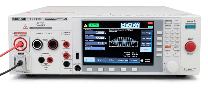
Figure 6a. Standby State — “READY” indicates that the test can be started by pressing the START button.
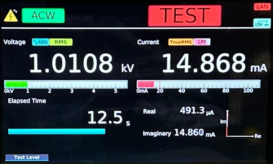
Figure 6b. Test in Progress — voltage and current are continuously displayed; the elapsed time advances after the START button is pressed.

Figure 6c. PASS — The test has ended after the configured duration. Displaying the results.
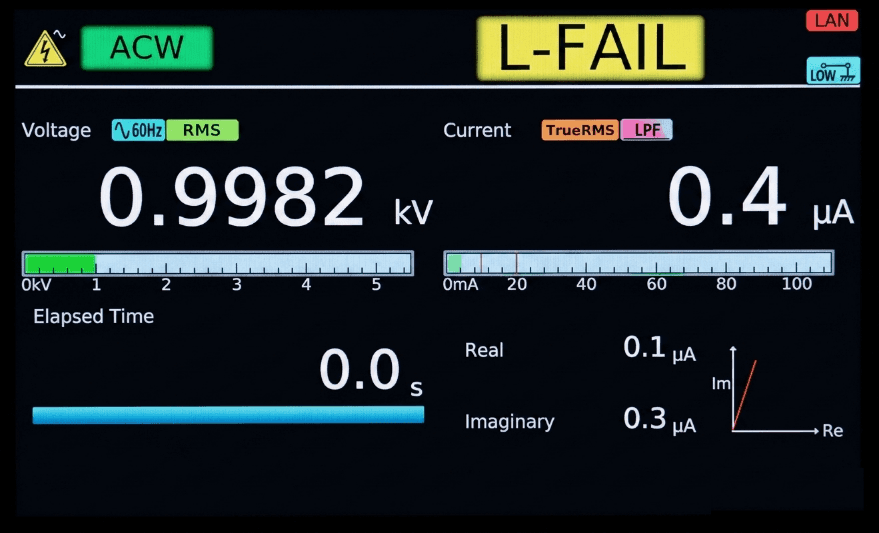
Figure 6d. L-FAIL — Test stopped because the test current dropped below the lower limit (10 mA).
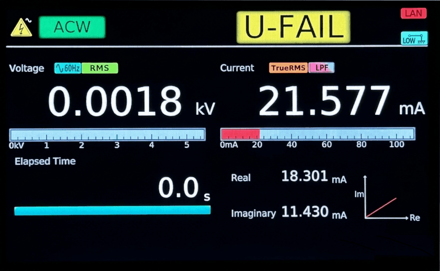
Figure 6e. U-FAIL — Test stopped because the test current exceeded the upper limit.
5. Precautions During Testing
The following points require attention during the withstand voltage test.
- Do not touch the DUT or cables while testing is in progress.
- Ensure that the DUT and cables are securely connected.
- Display a warning indicating that a withstand voltage test is being conducted to prevent bystanders from touching the DUT or cables.
- If there are three or more test points, exercise caution, as residual charge may accumulate in areas other than the specific sections currently under test.
6. Troubleshooting & FAQ
Common questions about AC withstand voltage testing, capacitive current, and test-limit configuration.
Q1. Why does my test fail intermittently on the production line?
Intermittent failures are often caused by variations in Y-capacitor tolerances (typically ±10% or ±20%). When the upper current limit is set too close to the nominal calculated value, units with capacitance on the high end of the tolerance range may be falsely judged as failures. Setting an appropriate safety margin (e.g., 20% to 30%) above the calculated nominal current helps reduce such false judgments caused by component tolerance variations.
Q2. How can I distinguish capacitive current from a real insulation breakdown?
If a withstand voltage test results in a failure, it is important not to rely solely on the preset current threshold, but to evaluate the characteristics of the measured test current. A true insulation breakdown produces leakage current with a significant active (real) current component, whereas capacitive effects are dominated by reactive (imaginary) current. By assessing whether the measured current matches expected capacitive behavior or indicates an abnormal leakage path, engineers can determine whether the failure is due to threshold settings or a genuine issue with the DUT. Advanced testers, such as the Kikusui TOS9300 series, support this analysis through True RMS measurement and on-screen separation of Real and Imaginary current components, helping engineers accurately identify the nature of the current while avoiding unnecessary rework and ensuring true insulation defects are not overlooked.
Q3. What is the most efficient way to test a DUT with multiple test points?
Manually swapping cables between the primary, secondary, and chassis grounds is slow and introduces operator error. Utilizing a high-voltage matrix scanner automates the sequential testing of multiple points under a single test program.
Conclusion & Key Takeaways
Designing a safe and highly efficient hipot test requires more than just connecting leads and pressing start. To ensure absolute compliance and protect production yields, remember these key takeaways:
- Calculate, Don’t Guess — Always calculate the expected capacitive current based on the total line-to-ground capacitance and test frequency to establish an accurate baseline.
- Use Upper AND Lower Limits — Implement an upper limit (U-FAIL) to catch dielectric breakdown, and a lower limit (L-FAIL) to immediately detect disconnected test leads or open circuits.
- Differentiate the Objective — Use a 60-second test duration during Type Testing to validate insulation design, but utilize 1-second tests during Routine (Mass Production) Testing to efficiently catch manufacturing defects.
Why Kikusui?
Since 1949, Kikusui Electronics Corporation has been a global leader in electronic test and measurement instruments, renowned for uncompromised Japanese manufacturing quality and reliability.
Operating out of Torrance, California, Kikusui America, Inc. provides the North American market with direct access to specialized application engineers, rapid local support, and deep expertise in electrical safety testing automation.
Our Safety Tester Lineup
| Series | Description |
|---|---|
| TOS9300 Series — Flagship multi-function safety analyzer | The ultimate multi-function analyzer. Combines AC/DC Withstand Voltage, Insulation Resistance, Ground Bond, and Leakage Current testing in a single unit. Features advanced color displays and vector current analysis (Real vs. Imaginary current separation) — directly addressing the capacitive-current challenge described in this paper. |
| TOS5400 Series — Next-generation production standard | The highly anticipated successor to the industry-standard TOS5300 series. Designed with PWM amplifier technology for highly stable, low-distortion output independent of AC power line fluctuations — perfect for high-speed mass production lines. |
Ready to Optimize Your Testing Process?
Stop letting false fails impact your bottom line and ensure your products meet the highest safety standards. Our Torrance-based application engineers are ready to review your current test parameters or assist with automating your production line.
- → Request a Free Application Consultation — Have our engineers review your specific DUT schematics to optimize your hipot test limits.
- → Request a Demo Unit — Test-drive the TOS9300 or TOS5400 series on your own production floor.
- → Connect with Our Team — Discuss automation options for multi-point testing, scanners, and full production-line integration.

