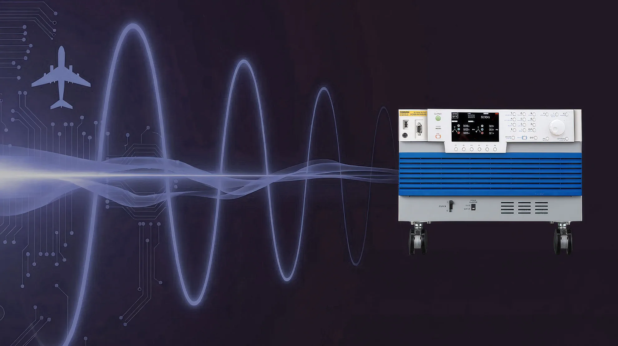
MIL-STD-704F / RTCA DO-160G
Avionics Power Quality Test Solutions
Kikusui PCR-WEA2 Series — Single Platform for 360–800 Hz Variable Frequency, Fixed 400 Hz, 60 Hz, and DC Testing
- MIL-STD-704F (Rev. F) defines test requirements for variable frequency (wild frequency) AC buses operating from 360–800 Hz, in addition to fixed 400 Hz, 60 Hz, and DC (28 V / 270 V) systems. Where variable frequency is the chosen primary AC system, the test power source must support output frequencies up to 800 Hz.
- The Kikusui PCR-WEA2 Series covers 1 Hz–5,000 Hz output frequency, supporting all MIL-STD-704F AC test groups (fixed 400 Hz, variable 360–800 Hz, single-phase 60 Hz) and RTCA DO-160G Section 16 power input requirements (AC and DC) in a single unit.
- The SD012-PCR-WE Avionics Test Software (Ver. 2.0x) enables GUI-based configuration of MIL-STD-704A/E/F, RTCA/DO-160F/G, and JIS W0812:2004 test sequences, with built-in test automation, CSV log files during execution, and test reports that can be exported to Excel, PDF, or Word.
What is MIL-STD-704F — Military Aircraft Power Quality Standard
MIL-STD-704F is the U.S. Department of Defense interface standard for military aircraft electric power characteristics. It applies to U.S. military aircraft electric utilization equipment, both fixed-wing and rotary-wing.
MIL-STD-704 (Aircraft Electric Power Characteristics) is a DoD interface standard covering aircraft electric power characteristics at the input terminals of electric utilization equipment. First issued in 1959, it has been continuously updated; the current revision MIL-STD-704F was published on 12 March 2004 and updated by Change Notice 1 on 5 December 2016.
The most significant change introduced by Revision F is the addition of test requirements for variable frequency AC buses (360–800 Hz) and an alternate 115 Vac / 60 Hz single-phase system intended for commercial-off-the-shelf (COTS) equipment aboard the aircraft. Variable frequency systems couple generators directly to the engine shaft—eliminating the constant-speed drive and reducing system weight—and have become common in modern fighters, transports, and large airliners.
Note that variable frequency, double-voltage (230/400 V), and 60 Hz systems are defined as alternative power systems in MIL-STD-704F. The standard does not require all aircraft to use variable frequency; rather, it specifies the requirements that apply when variable frequency is the chosen primary AC bus.
| Item | Pre-Rev. F | Rev. F (Current) |
|---|---|---|
| Fixed 400 Hz, 115/200 V (single & three phase) | Applicable | Applicable (continued) |
| Variable Frequency 360–800 Hz, 115/200 V | Not specified | Newly added in Rev. F — requires test source capable of output up to 800 Hz |
| Single-phase 115 V / 60 Hz (for COTS equipment) | Not specified | Newly added in Rev. F |
| 28 V DC and 270 V DC systems | Applicable | Applicable (continued) |
| Double-voltage 230/400 V, 400 Hz | Defined as alternative | Defined as alternative AC system |
“Where the aircraft uses a variable frequency primary AC bus, the test power source must continuously sweep from 360 to 800 Hz at the rates specified by the standard. Conventional fixed 400 Hz power supplies cannot satisfy these Rev. F test requirements.”
Why High-Frequency Output Capability is Required for Test Power Sources
Aircraft generators directly coupled to engine shafts produce a frequency that varies with engine speed. In MIL-STD-704F, the variable-frequency primary AC bus is specified for 360 Hz to 800 Hz operation (commonly referred to as the “wild frequency” or “WF” band). RTCA/DO-160G distinguishes between two variable-frequency designations: A(NF) — narrow variable frequency, 360–650 Hz — and A(WF) — wide variable frequency, 360–800 Hz.
Onboard equipment connected to a variable frequency bus (navigation computers, radar power supplies, electric actuators, environmental control units, etc.) must demonstrate normal operation across this frequency range. The test power source must therefore be capable of:
- Sweeping from 360 Hz to 800 Hz at the rate specified by the standard. Per MIL-STD-704F Table II, the maximum rate of change of frequency is 250 Hz/sec under normal transient conditions; per §5.2.4, abnormal frequency transients are limited to 500 Hz/sec.
- Maintaining stable output voltage at each frequency (115 V L-N / 200 V L-L for the standard variable-frequency system). Note: many programmable AC sources (including the PCR-WEA2 in its uncorrected response) begin to exhibit voltage drop above 500 Hz; for accurate testing in the 800 Hz band, the voltage correction function should be used.
- Applying voltage steady-state and transient envelopes, frequency deviations, voltage waveform distortion (distortion factor ≤ 0.05), and three-phase unbalance independently.
- Reproducing transient voltage and frequency events with sub-cycle step response (the inverter must follow the leading edge of voltage steps within a few milliseconds), and accurately tracking the standard’s recovery envelopes (e.g., returning to steady-state within 87.5 ms — approximately 35 cycles at 400 Hz — per MIL-STD-704F Figure 3).
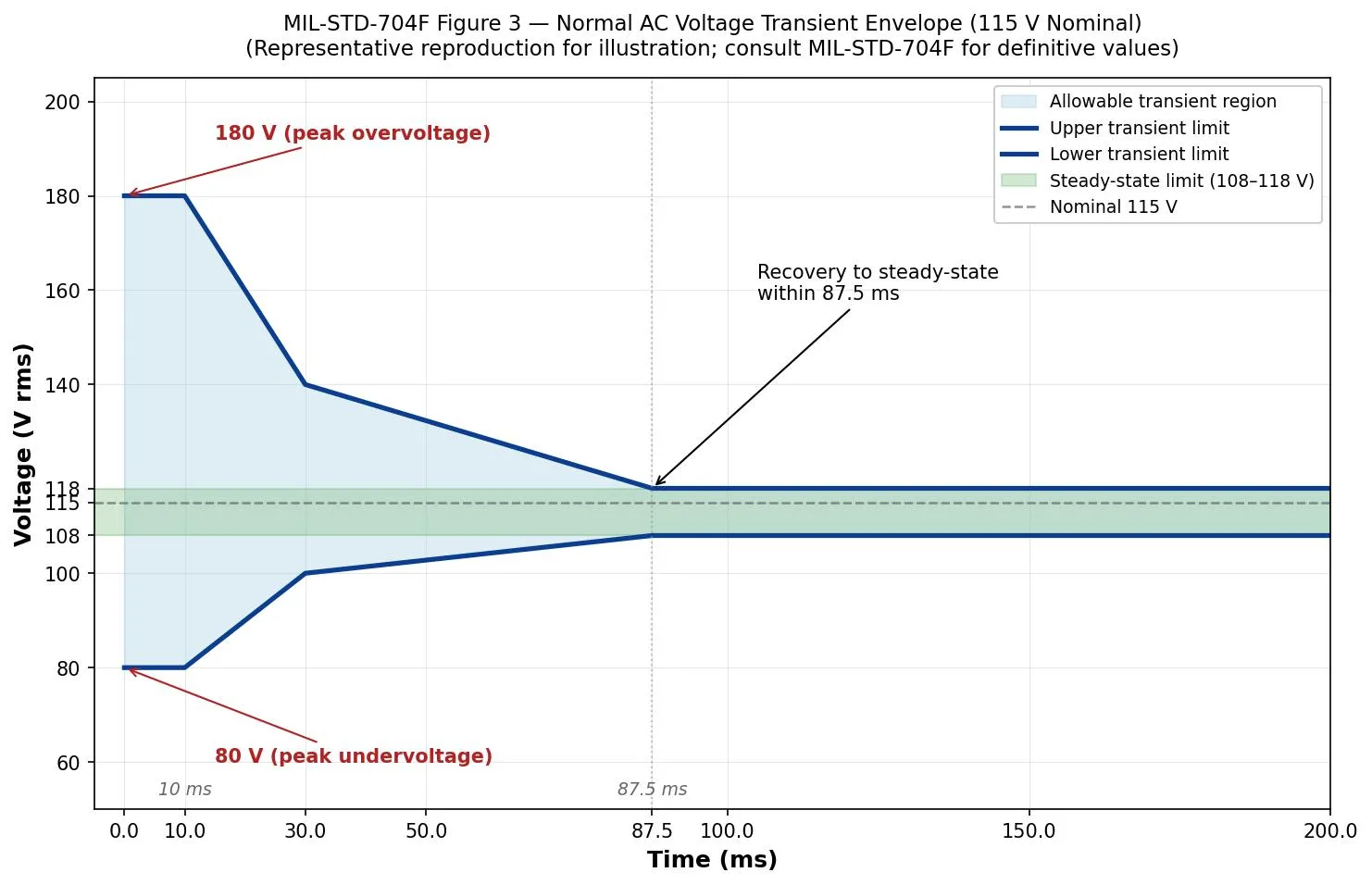
Figure: Representative reproduction of MIL-STD-704F Figure 3 — Normal AC Voltage Transient Envelope (115 V Nominal). Test power sources must reproduce envelope events that recover from peaks of 180 V (overvoltage) or 80 V (undervoltage) back to the steady-state band (108–118 V) within 87.5 ms. Consult MIL-STD-704F for definitive values.
| Test Parameter | Fixed 400 Hz Power | PCR-WEA2 (1 Hz–5 kHz) |
|---|---|---|
| Fixed 400 Hz, 115/200 V | ✓ Supported | ✓ Supported |
| 360–800 Hz Variable Frequency Sweep (250 Hz/s normal, 500 Hz/s abnormal rate of change) | ✗ Not supported | ✓ Supported |
| Sub-cycle Voltage / Frequency Transients (Figure 3 envelope, 80–180 V over 10–87.5 ms) | ✗ Not supported (insufficient response) | ✓ Supported (high-speed response) |
| High-frequency harmonic injection above 400 Hz | ✗ Not supported | ✓ Supported (arbitrary waveform mode) |
| Single-phase / Three-phase switching via software | Model dependent | ✓ Software-configurable (3 kVA and above) |
| DC output (for 28 V / 270 V test groups) | Model dependent | ✓ All modes: AC / DC / AC+DC |
Kikusui PCR-WEA2 Series — MIL-STD-704F-Compliant Power Supply Solution
The PCR-WEA2 is a PWM inverter-type AC/DC power supply with an output frequency range of 1 Hz–5,000 Hz. The 6 kVA model fits in 6U; single-unit ratings extend up to 36 kVA, and parallel expansion is supported up to 144 kVA in standard mix-and-match configurations (and up to 540 kVA when more than four units are combined, by special configuration).
The Kikusui PCR-WEA2 Series is a high-density PWM inverter-type programmable AC/DC power supply that supports avionics power quality testing on a single platform. The Avionics Test Software (SD012-PCR-WE Ver. 2.0x) requires PCR-WEA series firmware version 3.10 or later.
Kikusui PCR-WEA2 Series — a high-density PWM inverter-type programmable AC/DC power supply built for MIL-STD-704F and RTCA DO-160G avionics power quality testing on a single platform.
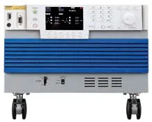
- Output frequency: 1 Hz–5,000 Hz
- Output voltage: 0–320 Vrms (AC) / 0 to ±452 V (DC)
- Power range: 1 kVA–36 kVA (up to 144 kVA in standard parallel operation)
- Regenerative model (PCR-WEA2R) available for 100% power regeneration
| Key Specifications | PCR-WEA2 |
|---|---|
| Output Method | PWM Inverter (switching) |
| Output Frequency | 1 Hz–5,000 Hz (covers all MIL-STD-704F AC frequency groups) |
| Output Voltage (AC) | 0–320 Vrms (L-N); L range 0–160 V / H range 0–320 V (limit setting up to 322 V) |
| Output Voltage (DC) | 0 to ±452 V (limit setting up to ±455 V) |
| Output Mode | AC / DC / AC+DC (DC superimposition mode) |
| Power Range (Single Unit) | 1 kVA–36 kVA |
| Power Range (Parallel) | Up to 144 kVA in standard mix-and-match operation (max 4 units); up to 540 kVA by special configuration (consult Kikusui for >4 units in parallel) |
| Phase Switching | Single-phase / single-phase 3-wire / three-phase, software-configurable on multi-type models 3 kVA and above |
| Regenerative Function | PCR-WEA2R model: 100% power regeneration capability; overall device efficiency approximately 85%; regenerated energy is fed back to the on-site grid only |
| Voltage Correction Function | Built into SD012-PCR-WE; corrects output voltage to within ±1% of the test value at high frequencies (above ~500 Hz where the inverter response begins to roll off). Required for accurate testing in the 800 Hz range and above. |
| Digital Interface | LAN (LXI) / USB / RS-232C / GPIB (factory option) |
| Web Interface | Direct control and monitoring via web browser (no driver installation required) |
MIL-STD-704F Power Group Coverage
MIL-STD-704F itself is organized around four data tables (Table I: 400 Hz; Table II: variable frequency; Table III: 60 Hz; Table IV: DC). Its companion test guidance handbook MIL-HDBK-704 (parts 1–8) defines seven power groups for compliance testing — these are the designators used by the SD012-PCR-WE Avionics Test Software. The PCR-WEA2 supports all of them.
| Power Group (per MIL-HDBK-704) | Designator | Power Conditions | PCR-WEA2 Support |
|---|---|---|---|
| Single-phase, fixed 400 Hz | SAC | 115 Vrms / 400 Hz / single-phase | ✓ Standard |
| Three-phase, fixed 400 Hz | TAC | 115/200 Vrms / 400 Hz / three-phase | ✓ Three-phase output mode |
| Single-phase, variable 360–800 Hz | SVF | 115 Vrms / 360–800 Hz / single-phase | ✓ Via 1–5,000 Hz output range |
| Three-phase, variable 360–800 Hz | TVF | 115/200 Vrms / 360–800 Hz / three-phase | ✓ Three-phase output at high frequency |
| Single-phase, 60 Hz (COTS equipment) | SXF | 115 Vrms / 60 Hz / single-phase | ✓ Standard |
| 28 V DC | LDC | 28 V DC / two-wire or negative-ground return | ✓ DC mode |
| 270 V DC | HDC | 270 V DC / two-wire or negative-ground return | ✓ DC mode (within 0 to ±452 V range) |
MIL-HDBK-704 also defines six aircraft electrical operating conditions, which determine the test number assigned to each test in the Avionics Test Software:
| Operating Condition | Test Number | Examples |
|---|---|---|
| Normal | 1xx | Steady-state limits, modulation, voltage/frequency transients, distortion |
| Transfer | 2xx | Power interrupt during bus transfer (≤ 50 ms per §5.1.1.1) |
| Abnormal | 3xx | Abnormal voltage/frequency limits, abnormal transients |
| Emergency | 4xx | Emergency operation limits |
| Starting | 5xx | Engine starting voltage transients (DC groups only) |
| Power Failure | 6xx | Total or partial power failure, phase reversal |
Note: “Group I–V” terminology used by some third-party software vendors (e.g., Pacific Power Source SmartSource Suite) is not the official MIL-STD-704F nomenclature. MIL-STD-704F uses Tables I–IV; MIL-HDBK-704 uses the SAC/TAC/SVF/TVF/SXF/LDC/HDC designators shown above.
Key Test Items and Parameters (MIL-STD-704F)
Test parameters for each item can be recalled as pre-configured sequences in the SD012-PCR-WE Avionics Test Software. No manual programming required.
The key test items specified by MIL-STD-704F (and detailed in MIL-HDBK-704 parts 1–8) are summarized below. The combination of PCR-WEA2 and SD012-PCR-WE enables all of these to be sequenced and run automatically.
| Test Item | Test Conditions (Rev. F representative values) | Implementation with PCR-WEA2 |
|---|---|---|
| Steady-State Voltage | 400 Hz & VF: 108.0–118.0 Vrms (Tables I & II); 60 Hz: 105.0–125.0 Vrms (Table III). Abnormal limits per Figures 4 and 9. | Voltage setpoint changed sequentially via sequence |
| Steady-State Frequency (Variable Frequency) | Sweep across the full 360–800 Hz range; frequency modulation 4 Hz max; max rate of change 250 Hz/sec normal (§5.2.3) / 500 Hz/sec abnormal (§5.2.4) | 1–5,000 Hz frequency sweep function with programmable rate |
| Normal Voltage Transient (TAC109 / SAC109) | Step changes from 115 V to 140 V, 160 V, 180 V (overvoltage) and to 80 V (undervoltage); recovery to steady state within 87.5 ms (Figure 3 envelope) | Sub-cycle voltage transient sequence |
| Power Interrupt during Transfer (xxx201) | During power transfer, voltage and frequency shall not vary between zero and normal operating limits for longer than 50 ms (§5.1.1.1). Power-failure tests (xxx601) in MIL-HDBK-704 cover longer outages (e.g. 100 ms / 500 ms / 3 s / 7 s). | Output on/off sequenced with programmable interrupt duration |
| Voltage Distortion / Distortion Spectrum | Distortion factor ≤ 0.05 (5%); distortion spectrum per Figure 7 for 400 Hz / VF, Figure 12 for 60 Hz | Arbitrary waveform mode with programmable harmonic content (1st–50th order) |
| Voltage Unbalance and Phase Difference (three-phase) | Voltage unbalance ≤ 3.0 Vrms; phase difference 116°–124° (Tables I & II) | Independent per-phase control in three-phase output mode |
| Frequency Rate of Change | Variable frequency: 250 Hz/sec normal, 500 Hz/sec abnormal | Frequency sweep rate set via sequence (covers entire MIL-STD-704F range) |
| Combined Voltage and Frequency Variation | Simultaneous application of voltage and frequency variation per applicable envelopes | Combined voltage and frequency sequence |
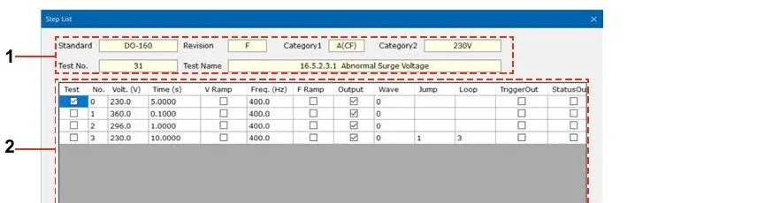
Figure: Step List Editing Window — Test standard, voltage, time, frequency, loop, and more can be edited visually.
SD012-PCR-WE Avionics Test Software — Test Sequence Automation
The SD012-PCR-WE Avionics Test Software (Ver. 2.0x) is a GUI-based test execution and sequence management tool. It contains built-in test sequences for MIL-STD-704A/E/F, RTCA/DO-160F/G, and JIS W0812:2004, and includes step list editing, waveform preview, arbitrary waveform creation, output voltage correction, CSV log files during execution, and test reports that can be exported to Excel, PDF, or Word. USB dongle key authentication is required.
Two product variants exist: SD012-PCR-WE for the PCR-WEA/WEA2 series, and SD012-PCR-LE for the PCR-LE/LE2 series. Both share the same test library and user interface, and are sometimes jointly referred to as SD012-PCR-LE/WE in product literature.
Just as Pacific Power Source’s SmartSource Suite reduces operator time with pre-configured sequences, Kikusui delivers comparable automation with the SD012-PCR-WE Avionics Test Software.
| Feature | Description |
|---|---|
| Graphical Step Editor | Visually configure time-series changes in voltage, frequency, and phase. Each step supports V Ramp, F Ramp, Output on/off, Trigger Out, and Status Out signals. |
| MIL-STD-704A/E/F Sequence Library | Standard test sequences for each of the 7 MIL-HDBK-704 power groups (SAC, TAC, SVF, TVF, SXF, LDC, HDC) recallable as pre-built templates |
| RTCA DO-160F/G Section 16 Support | Section 16 power input test sequences for AC categories A(CF) / A(NF) / A(WF) and DC categories A / B / D / Z are configurable |
| JIS W0812:2004 Support | Domestic Japanese aircraft equipment power input test sequences (corresponds to DO-160 Rev. D) |
| Voltage Correction Function | Compensates for the PCR-WEA’s high-frequency voltage roll-off (the manual notes output voltage may drop below -1% above 800 Hz). Correction data files are provided for both MEDIUM and FAST response speeds, and for use with or without the OT03-PCR-WEA transformer. |
| Arbitrary Waveform Creation | Three types: Peak-Cut SineWave, Harmonic (1st–50th order, level 0–100%, phase 0–359.9°), and Arbitrary (16-bit × 4096-point waveform data, importable from oscilloscope text files) |
| Automatic Execution and Logging | Automatically executes test sequences. With “Save Log File” enabled, voltage/current/power/frequency data is recorded to a CSV file (filename format: Standard-TestID.YYYYMMDD.HHMMSS.csv) |
| Test Report Output | Generates a Test Report viewable in the application after each test completes. Reports can be exported to Excel, PDF, or Word format using the toolbar Export function. Reports include standard info, test name, date, EUT/company/engineer/memo, supply source info, and full step list. |
| Aging / Warm-up Timer | “Set Time of” timer (1–9999 sec) applies the EUT’s nominal voltage for a set duration before starting the actual test sequence |
| Repeat / Trigger / Status Sync | Repeat count 1–9999; per-step trigger output (DIO.1) and status output (DIO.2) for synchronization with external test equipment |
| Remote Control (SCPI / IVI) | Programmatic control via IVI-COM / IVI VISA 5.0; supported over LAN (LXI), USB, RS-232C, and GPIB (factory option) |
| Simulation Mode | If no PCR-WEA is connected, the software automatically starts in simulation mode, allowing test sequences to be edited and reviewed without hardware (USB dongle key still required for full functionality) |
| Web Browser Control | Direct operation via Chrome/Edge from the PCR-WEA2 built-in web server (no software installation required) |
“With the SD012-PCR-WE Avionics Test Software, there is no need to manually program sequences for each MIL-STD-704F test group from scratch. Simply recall a template, adjust the voltage and current limits to match the DUT specifications, and testing can begin.”
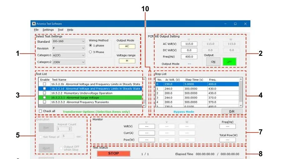
Figure: SD012-PCR-WE Avionics Test Software Main Window (test standard selection, phase, test list, step list, output monitor, execution control).
RTCA DO-160G Section 16 — Civil Aviation Avionics Testing
RTCA DO-160G is the environmental and electrical test standard for civil aircraft airborne equipment. Section 16 specifies power input tests for both AC and DC equipment, with content closely related to MIL-STD-704F.
While MIL-STD-704F targets military aircraft, RTCA DO-160G (Environmental Conditions and Test Procedures for Airborne Equipment, RTCA, 2010, identical to EUROCAE ED-14G) is the corresponding standard for civil aircraft airborne equipment, referenced in FAA and EASA type certification. Section 16, “Power Input,” classifies equipment into seven categories:
| Category | Description | PCR-WEA2 Support |
|---|---|---|
| A(CF) | AC equipment for constant 400 Hz primary AC system | ✓ Standard |
| A(NF) | AC equipment for narrow variable frequency (360–650 Hz) | ✓ Standard |
| A(WF) | AC equipment for wide variable frequency (360–800 Hz) | ✓ With voltage correction at upper frequencies |
| A | 28 V DC equipment from a constant or variable frequency AC system | ✓ DC mode |
| B | 14 V or 28 V DC equipment with battery on the bus | ✓ DC mode |
| D | 270 V DC equipment from a constant or variable frequency AC system | ✓ DC mode |
| Z | 28 V DC equipment for other system types | ✓ DC mode |
The PCR-WEA2 + SD012-PCR-WE system supports RTCA DO-160G Section 16 test requirements in addition to MIL-STD-704F, enabling manufacturers and test laboratories with both military and civil aircraft programs to perform certification tests on a single system.
Tests requiring the optional OT03-PCR-WEA step-up transformer are explicitly identified by the SD012-PCR-WE software and are limited to four specific items. For a 230 V system, the DO-160 abnormal surge test requires an applied voltage of up to 360 V — twice the 180 V level used for a 115 V system — which exceeds the PCR-WEA’s 320 V maximum AC output. The OT03-PCR-WEA steps the voltage up by a 1:1.34 ratio (to a maximum of approximately 440 V), and the SD012 voltage correction function keeps the output stable to within ±1 % even in the 800 Hz band:
| Standard / Revision | Category | Test Items Requiring OT03-PCR-WEA |
|---|---|---|
| RTCA DO-160 F/G | A(CF) / A(NF) / A(WF) — 230 V, single or three phase | 16.5.1.5.1 Normal Surge Voltage; 16.5.2.3.1 Abnormal Surge Voltage |
| JIS W0812:2004 | A(CF) / A(NF) / A(WF) — 230 V, single or three phase | 16.5.1.5.1 Normal Surge Voltage; 16.5.3.3.1 Abnormal Surge Voltage |
Avionics Test Standards Comparison
| Applicable Standard | Application | Main Test Content | PCR-WEA2 Support |
|---|---|---|---|
| MIL-STD-704F (w/ Change 1, 2016) | U.S. military aircraft (fixed-wing and rotary-wing) electric utilization equipment | Fixed 400 Hz; variable 360–800 Hz; 60 Hz; 28/270 VDC; voltage/frequency steady-state and transient; unbalance; transfer interrupt | ✓ |
| MIL-STD-704A / 704E | Earlier revisions of MIL-STD-704 (some legacy equipment specifications) | AC and DC test sequences corresponding to each revision | ✓ (built into SD012-PCR-WE) |
| RTCA DO-160G Section 16 / EUROCAE ED-14G | Civil aircraft airborne equipment (FAA / EASA certification) | Power input (AC and DC): voltage steady-state and transient, frequency variation, momentary interruptions, voltage distortion, inrush, harmonics | ✓ |
| RTCA DO-160F | Earlier revision of DO-160 (legacy commercial avionics qualifications) | Same general structure as DO-160G with minor revision differences | ✓ (built into SD012-PCR-WE) |
| Airbus ABD0100.1.8 | Airbus A380 airborne equipment (largely based on DO-160 Section 16) | AC and DC power tests for A380 electrical system | ✓ (within frequency range; user-defined sequences) |
| Airbus ABD0100.1.8.1 | Airbus A350 airborne equipment | A350 electrical system, including variable-frequency support | ✓ (user-defined sequences) |
| Boeing 787B3-0147 | Boeing 787 Dreamliner airborne equipment | 787 power quality and design requirements (variable-frequency 360–800 Hz, 115 V and 235 V AC, 28/270 VDC) | ✓ (with OT03-PCR-WEA for 230/235 V tests) |
| MIL-STD-1399/300-1 (current; replaces 1399-300B from 2018) | U.S. Navy shipboard equipment | Type I (115/440 V, 60 Hz), Type II (115/440 V, 400 Hz), Type III (400 Hz, tighter tolerance) AC power characteristics | ✓ (60 Hz and 400 Hz supported) |
| JIS W0812:2004 | Japanese civil aircraft airborne equipment (corresponds to DO-160 Rev. D) | Environmental conditions and test procedures, including AC/DC power input | ✓ |
Why the PCR-WEA2 is a Strong Choice for Avionics Testing
1. 5,000 Hz Output Frequency — Wide Margin Above the 800 Hz Requirement
The PCR-WEA2 offers an output frequency range of 1 Hz–5,000 Hz, well above the 800 Hz upper limit specified by MIL-STD-704F variable-frequency systems. This provides ample headroom for harmonic testing and for next-generation aircraft architectures (such as more-electric aircraft and emerging high-frequency power systems). At frequencies above 500 Hz the inverter response begins to roll off, so the SD012-PCR-WE voltage correction function should be used to maintain accuracy in the 800 Hz band.
2. 6 kVA per 6U Chassis — Compact Switching Architecture
Conventional linear amplifier-type high-frequency power supplies require large cabinets to deliver 6 kVA. The PCR-WEA2 fits 6 kVA in a 6U (approximately 27 cm) chassis, with single-unit ratings up to 36 kVA. This compact footprint addresses floor-space constraints in aircraft production lines and test facilities.
3. Single-Phase / Three-Phase Switching via Software
On multi-type PCR-WEA2 models of 3 kVA and above, single-phase, single-phase three-wire, and three-phase outputs can be switched via software (the SD012-PCR-WE Settings → Wiring command sends the configuration to the unit). This allows a single unit to cover both single-phase test groups (SAC, SVF, SXF) and three-phase test groups (TAC, TVF) under MIL-HDBK-704, reducing facility cost and floor space.
4. Regenerative Model (PCR-WEA2R) — Reduced Energy Waste
Electromechanical aircraft components such as electric motor actuators (EMAs) and electric fuel pumps return power to the supply during braking. The PCR-WEA2R supports 100% power regeneration with no reverse-load time limit; regenerated energy is returned to the on-site grid (the device’s overall efficiency is approximately 85%, an improvement over previous PWM models). This eliminates large dummy-load resistors and reduces facility cooling load.
5. Parallel Expansion to 144 kVA (and beyond)
A single PCR-WEA2 unit delivers up to 36 kVA. Standard mix-and-match parallel operation with up to 4 units provides up to 144 kVA. For larger systems, expansion up to three-phase 540 kVA is possible by special configuration (consult Kikusui for combinations beyond 4 units in parallel). This supports system integration testing (SEIT) and ground power unit (GPU) testing of large military transport and patrol aircraft such as the Boeing C-17 (transport) and Kawasaki P-1 (maritime patrol).
Typical Test Setup — Complete MIL-STD-704F Test System
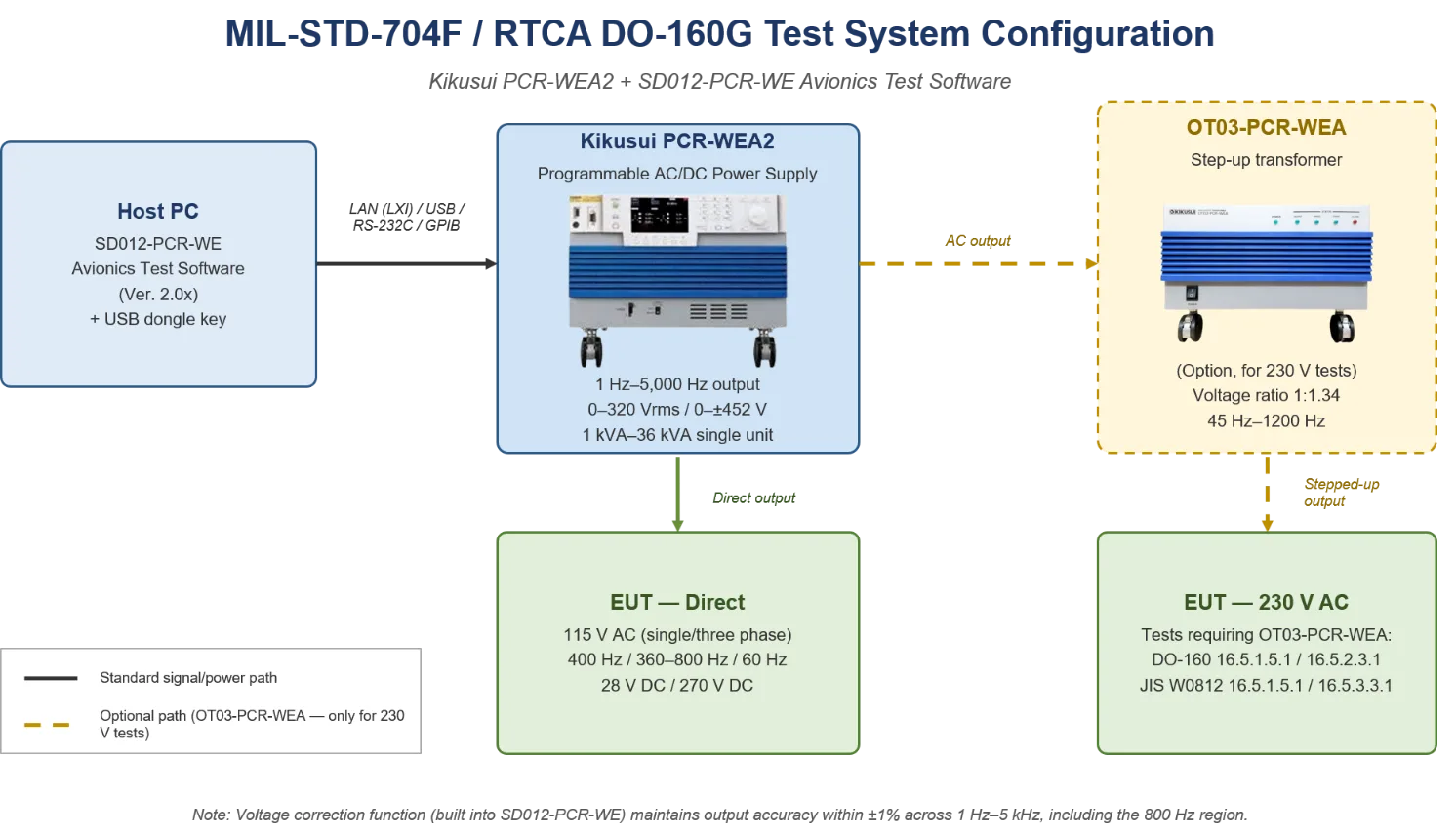
Figure: System configuration for MIL-STD-704F / RTCA DO-160G testing. The Host PC running SD012-PCR-WE controls the PCR-WEA2 over LAN/USB/RS-232C/GPIB. Most tests use the direct path to the EUT (115 V AC, 28/270 V DC); 230 V AC surge tests require the optional OT03-PCR-WEA step-up transformer.
| Component | Product / Specification | Role |
|---|---|---|
| Programmable AC/DC Power Supply | Kikusui PCR-WEA2 (or PCR-WEA2R), firmware Ver. 3.10 or later | Generates the voltage, frequency, and waveforms specified by MIL-STD-704F |
| Step-Up Transformer (Option) | Kikusui OT03-PCR-WEA (1:1.34 voltage ratio, 45 Hz–1200 Hz) | Required for 230 V single- or three-phase surge tests (DO-160 16.5.1.5.1 / 16.5.2.3.1, JIS W0812 16.5.1.5.1 / 16.5.3.3.1) |
| Test Sequence Software | SD012-PCR-WE Avionics Test Software (Ver. 2.0x); USB dongle key required | Creates, executes, logs, and reports test sequences for each test group |
| Power Measurement (Standard) | Kikusui PCR-WEA2 built-in measurement (V, A, W, VA, var, PF, harmonics) | Real-time measurement of DUT power consumption and harmonic current |
| Communication / Control | LAN (LXI) / USB / RS-232C / GPIB (factory option) | Integration with Automated Test Equipment (ATE) or host PC |
| High-Power System (Option) | PCR-WEA2 × multiple units in parallel | For testing high-power DUTs (aircraft subsystems, GPU, etc.) |
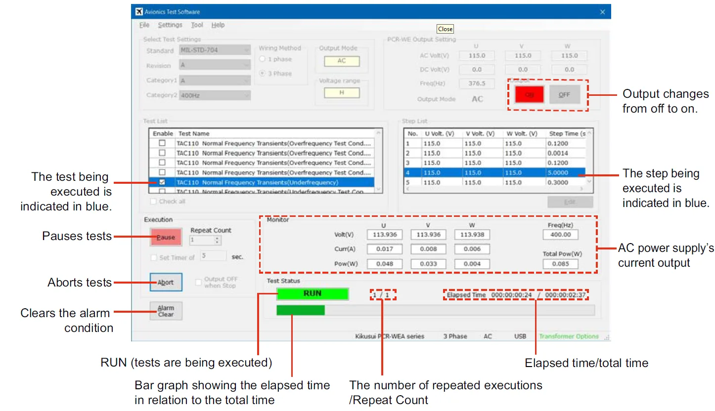
Figure: Main Window during test execution (RUN) — MIL-STD-704 test sequence running automatically. Real-time monitoring of test item, current step, voltage, current, and power.
Summary
MIL-STD-704F Revision F introduced test requirements for variable-frequency (“wild frequency”) AC buses operating from 360 Hz to 800 Hz, in addition to retaining specifications for fixed 400 Hz, 28/270 VDC, and adding the alternate 115 V / 60 Hz single-phase option for COTS equipment. Where variable frequency is the chosen primary AC bus, the test power source must support output up to 800 Hz with sub-cycle transient response and rate-of-change capability up to 250 Hz/sec (normal) or 500 Hz/sec (abnormal). Conventional fixed 400 Hz supplies and general-purpose programmable AC sources cannot meet these requirements.
The Kikusui PCR-WEA2 Series offers a 1 Hz–5,000 Hz output frequency range, up to 36 kVA single-unit power, software-selectable single/three-phase output, and an optional fully regenerative model (PCR-WEA2R), covering all MIL-STD-704F AC and DC test groups (SAC, TAC, SVF, TVF, SXF, LDC, HDC) and RTCA DO-160G Section 16 power input requirements (categories A(CF), A(NF), A(WF), A, B, D, Z) on a single platform. Combined with the SD012-PCR-WE Avionics Test Software (Ver. 2.0x), it significantly reduces test setup and sequence programming time, supporting the efficiency and reliability of avionics certification testing.
Frequently Asked Questions (FAQ)
Common questions about MIL-STD-704F, RTCA DO-160G, and Kikusui PCR-WEA2 avionics power-quality testing.
Q1. What is MIL-STD-704F?
MIL-STD-704F is the U.S. Department of Defense interface standard defining the electric power characteristics at the input terminals of military aircraft utilization equipment. The current revision was published on 12 March 2004 and updated by Change Notice 1 on 5 December 2016. It covers fixed 400 Hz, variable frequency 360–800 Hz, an alternate 115 V / 60 Hz single-phase system, and 28 V / 270 V DC systems.
Q2. What frequency range does the MIL-STD-704F variable-frequency (wild frequency) bus cover?
The variable-frequency primary AC bus is specified for 360 Hz to 800 Hz. A test power source must be able to sweep across this range at the standard’s maximum rate of change (250 Hz/sec under normal conditions, 500 Hz/sec under abnormal conditions) while holding a stable 115 V line-to-neutral / 200 V line-to-line output.
Q3. Can a single power source cover all MIL-STD-704F AC and DC test groups?
Yes. The Kikusui PCR-WEA2 Series outputs 1 Hz–5,000 Hz in AC, DC, and AC+DC modes, covering all seven MIL-HDBK-704 power groups (SAC, TAC, SVF, TVF, SXF, LDC, HDC) on a single platform, in addition to RTCA DO-160G Section 16 power-input tests.
Q4. What is the difference between MIL-STD-704F and RTCA DO-160G?
MIL-STD-704F is the U.S. military standard for aircraft electric power, while RTCA DO-160G (identical in wording to EUROCAE ED-14G) is the civil-aviation standard referenced in FAA and EASA certification. Their power-quality content is closely related: DO-160G Section 16 “Power Input” is the civil counterpart to the MIL-STD-704F test groups.
Q5. What is the difference between DO-160G categories A(NF) and A(WF)?
A(NF) (narrow variable frequency) covers 360–650 Hz, and A(WF) (wide variable frequency) covers 360–800 Hz. A(CF) is the constant-frequency 400 Hz category. The PCR-WEA2 supports all three through its 1–5,000 Hz output range.
Q6. Why is a step-up transformer (OT03-PCR-WEA) needed for 230 V testing?
For a 230 V system, the DO-160 / JIS abnormal surge test requires an applied voltage of up to 360 V—twice the 180 V level used for a 115 V system—which exceeds the PCR-WEA2’s 320 V maximum AC output. The OT03-PCR-WEA steps the voltage up by a 1:1.34 ratio (to a maximum of approximately 440 V), and the SD012 voltage-correction function holds the output within ±1 % even in the 800 Hz band. Only four test items require it: DO-160 16.5.1.5.1 and 16.5.2.3.1, and JIS W0812 16.5.1.5.1 and 16.5.3.3.1.
Q7. Why does a test power source need output capability above 400 Hz?
Modern aircraft use variable-frequency generators coupled directly to the engine shaft, so the bus frequency rises up to 800 Hz. Equipment must be verified across 360–800 Hz, and harmonic and transient testing benefits from additional headroom—the PCR-WEA2 provides up to 5,000 Hz. Above approximately 500 Hz the inverter output begins to roll off, so the SD012 voltage-correction function is used to maintain accuracy in the 800 Hz band.
Q8. Does the PCR-WEA2 support both single-phase and three-phase output?
Yes. On multi-type PCR-WEA2 models of 3 kVA and above, single-phase, single-phase three-wire, and three-phase output can be switched from the SD012-PCR-WE software, so one unit can run both the single-phase groups (SAC, SVF, SXF) and the three-phase groups (TAC, TVF).
Q9. What are the key output ratings of the PCR-WEA2?
AC output is 0–320 Vrms (line-to-neutral), DC output is 0 to ±452 V, and the output mode can be AC, DC, or AC+DC. Single-unit power ranges from 1 kVA to 36 kVA, with standard mix-and-match parallel operation up to 144 kVA (four units) and up to 540 kVA by special configuration.
Q10. Which test standards does the SD012-PCR-WE Avionics Test Software support?
It includes built-in, GUI-selectable test sequences for MIL-STD-704A/E/F, RTCA/DO-160F/G, and JIS W0812:2004 (which conforms to RTCA/DO-160D). Test reports can be exported to Excel, PDF, or Word, and a USB dongle key is required to run tests.
Reference Links
PCR-WEA/WEA2 Series Product Page (Kikusui America)
SD012-PCR-WE Avionics Test Software Product Page (Kikusui America)