
AI servers are getting dramatically more power-hungry. As a result, data centers are increasingly adopting high-voltage direct current (HVDC) power architectures—often ±400V or 800V—to deliver large amounts of power while reducing distribution losses.
Compared to traditional low-voltage power distribution, HVDC systems are advantageous because they deliver the same power at a higher voltage and lower current. Lower current reduces I²R losses, eases distribution constraints, and supports higher rack power density. In other words, the transition to HVDC systems means data centers can keep scaling power without turning the entire facility into a tangle of heavy cabling and heat.
However, the adoption of HVDC comes with new testing requirements. Teams need to prove that HVDC racks and power systems behave safely and predictably in order to confidently deploy them.
In this white paper, we explain the importance of HVDC server power testing and take a closer look at three challenges in particular:
- Establishing a workable HVDC test method
- Controlling energy and heat during long high-power tests
- Meeting safety and compliance requirements
The Move Toward HVDC in Data Centers
Data center power demands are increasing rapidly as AI workloads grow. In fact, the International Energy Agency (IEA) estimates that data center electricity will more than double from 415 TWh in 2024 to around 945 TWh by 2030.1 This growth isn’t just a future projection—globally, data center electricity consumption has been steadily increasing at roughly 12% per year since 2017.
At the rack level, AI infrastructure is pushing power density higher. Compared to the 5–10 kW range typical of traditional enterprise racks, AI racks can exceed 50 kW—even 100 kW—per rack.2 At these densities, the challenge isn’t just delivering power. Cooling capacity, physical infrastructure, and safety issues become limiting factors just as quickly as electrical design.3
In response, more operators and vendors are exploring HVDC “disaggregated power” approaches that centralize conversion and reduce losses to better support high-density racks. Microsoft has described this direction through its Mt Diablo (OCP Diablo 400) disaggregated power specification, co-authored with Meta and Google.4,5 Designed to scale IT racks from 100 kW up to 1 MW, the spec frames ±400V delivery as the foundation for a disaggregated power rack feeding a nearby IT rack.
However, a successful transition to HVDC requires testing HVDC systems under realistic operating conditions. Otherwise, teams risk uncovering performance, reliability, or safety issues after deployment.
Common Challenges Around HVDC Rack Testing & How to Approach Them
Testing HVDC racks requires test environments that can handle high voltage, high power, fast transients, and strict safety constraints—all at the same time. Given these requirements, validation can be difficult. Three common challenges tend to show up:
- Realistic transient simulation at HVDC levels
- Long-duration validation without excessive heat and energy costs
- Meeting OCP’s safety and compliance expectations
Next, we explore each challenge in detail and suggest solutions for overcoming them.
Challenge: Establishing a test method for ±400V / 800V racks with dynamic transients and bidirectional flow
Real server and rack workloads do not draw a perfectly steady amount of power. Demand can change in a matter of seconds, especially as large-scale AI clusters can exhibit extreme and rapid power swings.6 That means validation must include fast and repeatable load changes that mimic real behavior—not just slow ramps or steady-state points.
Many conventional test setups struggle to reproduce these transient conditions at the necessary voltage and power levels. When the test bench can’t reproduce the real conditions, teams typically run into two problems:
- Incomplete validation, meaning problems are discovered late or in the field
- Misleading results, causing teams to chase “failures” created by the test setup rather than the device under test (DUT)
Adding to the complexity, “±400V” isn’t always a single, simple output. In many HVDC rack designs, ±400V is created as two rails (+400V and –400V) around a midpoint (0V). That means validation is not only about reaching a target voltage—it is also about controlling how those rails behave during rapid changes.
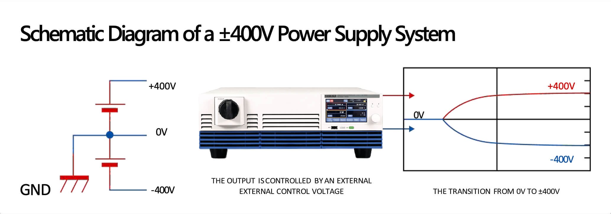
Figure 1. This schematic diagram of a ±400V power supply system illustrates that ±400V can be implemented as two rails (+400V and –400V) around a midpoint reference (0V).
It highlights that output behavior can be controlled by an external control signal, which makes ramp timing and sequencing part of what must be tested, not just steady-state voltage.
A credible test method must let engineers program and synchronize transitions to verify that the DUT remains stable and safe during these fast, real-world conditions.
Solution: Use a two-tool approach—one instrument for fast spikes, and a regenerative load for controlled steps
Because AI drives fast power fluctuations in servers, engineers should implement dynamic load testing that reproduces both fast spikes and controlled steps. This allows teams to observe whether the power supply remains stable as demand changes and whether protection features behave correctly under shifting conditions.
A practical way to do this is to use two tools, each serving a distinct testing function:
- One tool optimized for rapid changes, which helps stress the power supply and reveal extreme transient behavior
- Another tool optimized for repeatable step patterns over longer periods
Kikusui America offers measurement instruments designed to support HVDC power testing in all kinds of validation scenarios. For dynamic transients in particular, the PLZ-5WH2 series is best for simulating fast changes and high-stress load conditions.
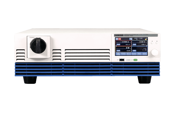
Kikusui America’s PLZ-5WH2 high-power DC electronic load series is designed for high-speed current response and realistic load simulation in large-capacity power supply and battery testing.

- Voltage: 10–1000V
- Slew rate: 20A/μs for fast transients
- Microsecond-level synchronization accuracy
- Ideal for point-of-load and PSU transient tests
In short, matching the right instrument to the specific transient behavior being evaluated will yield more accurate results than relying on a single setup to cover all test conditions.
In many cases, dynamic transient testing can be handled with an electronic load alone. However, some HVDC validation scenarios also involve cycling or recovery behaviors where the test bench must both deliver power and absorb it. In those cases, a bidirectional DC supply can simplify the setup by handling both sourcing and sinking in one system—a role the Kikusui PXB series is designed to support.
For controlled steps, the PXZ series regenerative electronic load from Kikusui America is ideal as it supports high-power, long-duration testing with its impressive energy efficiency. Because of its fast dynamic response modes and programmable I-V characteristics, it can reproduce controlled load steps and profiles with ease.
Kikusui America’s PXZ series of regenerative electronic loads provides programmable slew rates, fast dynamic response, and built-in sequence functions that enable precise, repeatable load transitions at high power levels.
- Voltage: 20–1000V
- Slew rate: Up to 60A/ms
- Efficiency 90% or higher
- Handles 20kW in 3U size
Challenge: Managing energy cost and thermal load during long-duration, high-power validation
For AI data centers, HVDC rack testing can be far more time-intensive than a simple component check. Validation may involve running server power supplies and battery systems at 100 kW-class power levels for extended periods—sometimes for days or even up to a week.
Given these long durations, the test setup itself becomes a cost and facility problem. If the test bench dissipates power as heat, the setup effectively becomes a large heater for days. That drives up direct electricity costs as well as a facility’s thermal management needs, e.g., HVAC and ventilation.
In other words, without the proper equipment, long testing runs can quickly become expensive and unsustainable.
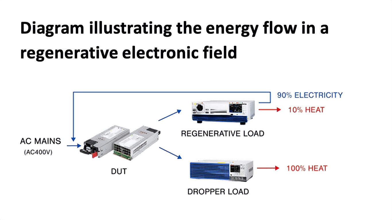
Figure 2. In a regenerative load, most absorbed energy is returned to the AC mains, reducing both energy waste and the facility’s cooling burden during long-duration, high-power tests. In a dropper load, absorbed energy becomes heat.
PXZ Regenerative Electronic Load
- Voltage classes: 500V / 1000V / 1500V
- >90% energy regeneration
- FAST mode: ~1 ms rise/fall, high slew presets for dynamic profiles
PXB Bidirectional DC Power Supply

- Source/Sink in one chassis, up to 1500V
- Battery Emulator (SD036PXB) for SOC/IV curves in BBU/DCDC tests
Solution: Use regenerative testing to reduce energy and cooling costs during extended runs
Regenerative systems, on the other hand, recapture and reuse much of the energy consumed during the test. This helps control direct energy costs and reduces cooling requirements, making regenerative systems ideal for tests running at very high power for extended periods.
Given AI server power needs, regenerative testing setups tend to be the optimal choice, which Kikusui America’s PXZ and PXB series are equipped to handle. Instead of dissipating absorbed power as heat, Kikusui America’s PXZ and PXB series of regenerative electronic loads return more than 90% of energy back to the facility power system. This helps to significantly reduce facility power consumption and save operating costs, especially for long-duration tests.
Challenge: Ensuring compliance with OCP HVDC standards while maintaining operator safety
HVDC testing has two separate but connected sources of risk: meeting OCP transient requirements reliably, and keeping the test bench safe for people and equipment.
We discuss both challenges and practical ways to address them below.
Compliance risk: executing transient tests correctly
OCP’s Diablo 400 specification defines dynamic load testing for ±400VDC power systems, including verifying power supply behavior under current transitions such as 1 A/µs. However, in practice, many engineering teams implement higher internal standards and test at slew rates above 1 A/µs.7
Meeting a slew rate requirement is not only a function of the electronic load’s specification. The physical test loop—especially cable inductance and wiring layout—can affect how fast current actually changes at the DUT and can introduce overshoot or ringing that distorts results.
OCP Diablo 400’s Dynamic Load Requirements
- Slew rate: 1 A/µs per PSU (baseline requirement)
- Step load cases: 50%, 90%, 140% step loads (with 10% minimum load condition)
- Frequency: up to 10 kHz (for defined step-load cases)
- Transient expectations: overshoot/undershoot limits and 3 ms settling time criteria are defined in the dynamic loading section
- Profiles: example dynamic and pulse load profiles are provided (duty cycle, frequency, timing windows)
Figures 3A and 3B show a simple example. In a 0A→50A step test, the achieved slew rate increased from approximately 1.3 A/µs to 3.1 A/µs after the wiring between the DUT and the electronic load was twisted to reduce inductance. This is why a high-speed test plan must include both appropriate instruments and a wiring approach that preserves transient performance.
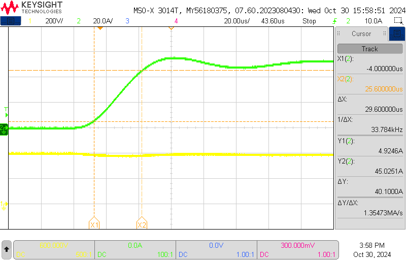
Figure 3A. Example 0A→50A load step showing showing an achieved slew rate of ~1.3 A/µs with A/µs with a standard wiring configuration.
If teams cannot execute these tests, they cannot confirm compliance with OCP or their internal requirements. That can delay development schedules and increase the risk of field failures.
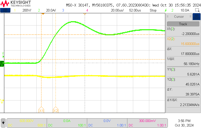
Figure 3B. Example 0A→50A load step showing an achieved slew rate of ~3.1 A/µs after twisting the wiring between the DUT and electronic load to reduce inductance.
Solution: Use low-inductance cables
To prevent overshoot and a drop in slew rate, it is important to use low-inductance cables specially designed for high-speed transient testing. Standard test leads can have inductance on the order of tenths of a microhenry per foot; low-inductance cables reduce that by roughly an order of magnitude by keeping the supply and return paths tightly coupled.
Low Inductance Cable (TL02-PLZ)
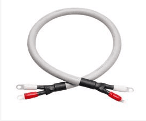
- Length: 1m
- Inductance: 0.15 uH
- Current carrying capacity: 100A
- Voltage rating: 500V
The goal is to reduce loop inductance: keep cables as short as possible, route supply and return together (for example, by twisting), and minimize loop area. These steps help ensure the DUT sees the intended load profile and that measurements are repeatable.
Safety risk: Keeping the test bench safe for operators
Working with HVDC systems presents a serious electric shock hazard. Any components that users interact with (such as PCs connected to test equipment) must be clearly and adequately isolated from the high-voltage section. Insufficient isolation can lead to leakage current or ground faults that put operators at risk and can damage both the DUT and test equipment.
Solution: Apply midpoint grounding and fault detection aligned with OCP’s Diablo 400
Proper grounding and fault detection create the conditions for safe, repeatable testing. Without them, the lab can become the weak link—even if the DUT itself is well designed.
The OCP Diablo 400 spec provides guidance for ±400V disaggregated power racks and includes detailed safety requirements around designing test environments.8
OCP Diablo 400’s Safety Guidance
- Ground fault detection is required to protect against fault conditions.
- HVDC grounding approach matters. Diablo 400 discusses midpoint grounding options (HRG vs. solid grounding) and notes the role of fault detection in safely resolving ground faults.
- Basic safety constraints apply. HV components should not be accessible while energized (use interlocks/power-off mechanisms where needed), and leakage current limits are specified.
The point is not that every lab must look identical, but that HVDC test benches should treat isolation, grounding strategy, and fault detection as foundational elements of an HVDC test bench.
Put simply: if the test environment cannot maintain safe separation between high-voltage rails and operator-facing interfaces, it is not ready for serious HVDC validation.
Securing the Future of AI with HVDC Power
HVDC is becoming increasingly important for modern AI data centers—but it can only be safely adopted when teams can validate performance under real conditions. As rack power density increases, organizations need test methods that can reproduce real operating behavior, run for long durations without runaway heat and cost, and meet OCP-aligned expectations while protecting operators and equipment.
1 International Energy Agency. April 10, 2025. “Energy and AI.”
2 ABB. December 9, 2025. “Powering the AI Revolution: Enhanced Protection for High-Density Data Center Infrastructure.”
3 David Eisenband. March 12, 2024. “100+ kW per rack in data centers: The evolution and revolution of power density.” Ramboll.
4 Ehsan Nasr. October 13, 2025. “Rethinking Power Conversion and Distribution for the AI Era.” Azure Infrastructure Blog.
5 Microsoft, Meta, Google. May 30, 2025. “Diablo 400 Project: Rack and Power.” Open Compute Project (OCP).
6 Daniel Bizo. November 19, 2025. “Electrical considerations with large AI compute.” Uptime Institute.
7 Microsoft, Meta, Google. May 30, 2025. “Diablo 400 Project: Rack and Power.” Open Compute Project (OCP).
8 Microsoft, Meta, Google. May 30, 2025. “Diablo 400 Project: Rack and Power.” Open Compute Project (OCP).

