

About the role of fuses
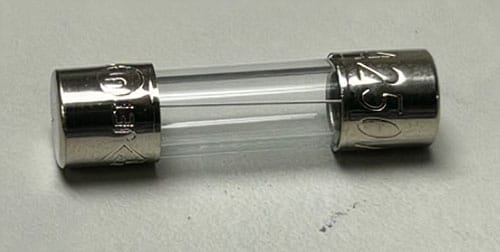
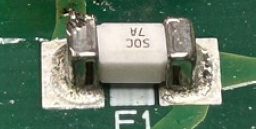
A fuse is a component used to protect electronic circuits.
When a current exceeding a certain level flows through it, the internal element melts, interrupting the circuit’s current.This prevents serious secondary damage (such as fire or electric shock).
Fuse Selection Method
Circuit designers first select the type of fuse based on the operating environment.
Many factors need to be considered, including whether it’s for DC or AC circuits, external dimensions, voltage rating, and current rating.
The fuse to be used is determined based on the datasheet provided by the fuse manufacturer.
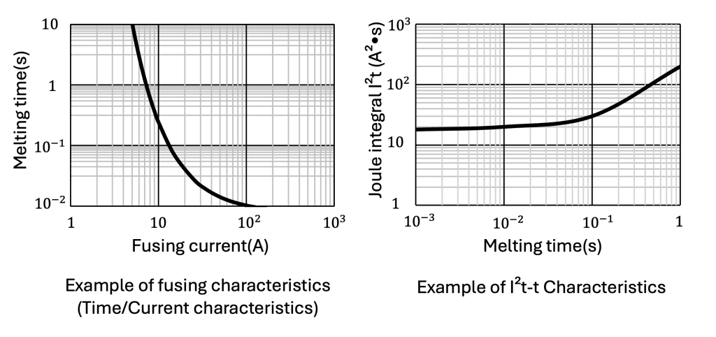
When determining the rated current of a fuse, the I²t value and the fusing characteristics diagram from the datasheet are used.Using these diagrams, the fuse selection is almost complete.However, fuse manufacturers ultimately require characteristic evaluation in the actual application.
Furthermore, derating may be applied depending on the operating environment, such as temperature, and the estimated usage time.
Method for evaluating the operation of a fuse in abnormal conditions
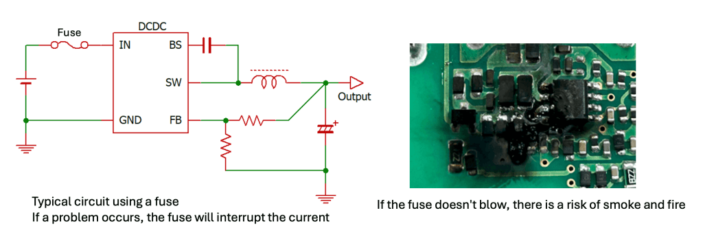
Evaluating whether a fuse blows can be done relatively easily by intentionally creating typical fault conditions in the circuit that the fuse protects. For example, if the circuit protected by the fuse is a DC-DC converter IC, the evaluation is complete if the fuse blows before the circuit burns out when the output of the DC-DC converter is short-circuited or when the pins of the DC-DC converter IC are short-circuited to cause a failure.
Method for evaluating that the fuse does not activate under normal conditions
Evaluating whether a fuse blows is easy, but evaluating whether it does not blow is not easy. When inrush current is applied to the fuse during power-up, an evaluation of this aspect is necessary, and it is essential to confirm that the fuse has sufficient margin in terms of temperature, lifespan, and inrush current.
If there is insufficient margin, the fuse may blow even when there is no abnormality, leading to equipment failure.
The temperature margin varies depending on the fuse, but for example, it would be a value such as 1.2 in a 50°C (122°F) environment. The lifespan margin is also a value between 1.1 and 1.3, depending on the fuse and the design margin.
Also, in relation to lifespan, inrush current is the current that flows now the equipment starts up, so the number of times the inrush current flows through the fuse can be estimated from the expected lifespan of the equipment and the assumed number of startups per day. It is also necessary to consider whether the fuse can withstand that number of cycles.
Due to these factors, proving that the fuse would not blow during design verification was a very difficult task.
However, using an electronic load makes such verification possible.
The following sections will explain this method.
A method for evaluating fuses using an electronic load
By following the steps below, you can repeatedly apply inrush current to the fuse and demonstrate that the fuse does not blow under normal operating conditions.
Step 1: Measure the inrush current flowing through the fuse
Measure the current flowing through the fuse being evaluated.
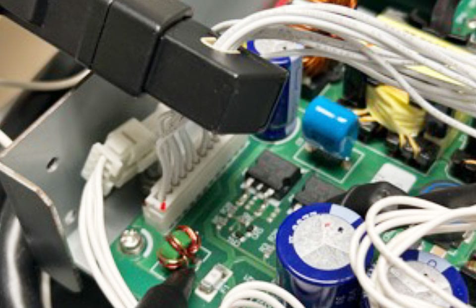
Measure current flowing through the fuse using a current probe. Generally, the largest current that flows through a fuse is the inrush current when the device is started.
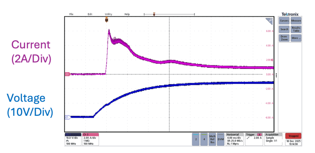
The current waveform data is extracted from the oscilloscope in numerical format. (Many oscilloscopes allow saving waveforms in CSV format)
Step 2: Apply derating to the measurement results
The waveform data output from the oscilloscope is multiplied by a derating factor.
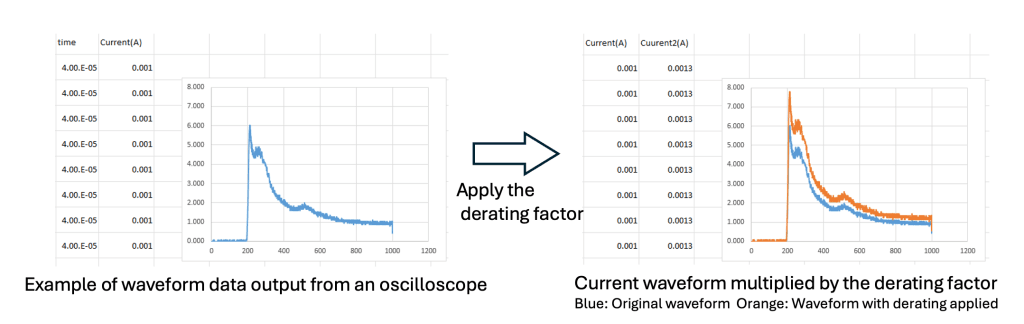
The derating factor varies depending on the operating temperature of the fuse, the lifespan of the equipment in which the fuse is installed, and the derating standards of each manufacturer.
Step 3: Program the current waveform into the electronic load
The waveform data is programmed into the electronic load. This time, we will be using the PLZ5W’s sequence function to simulate the load current, the sequence data will be created from a PC.

Step 4: Apply the current repeatedly to the fuse using the electronic load
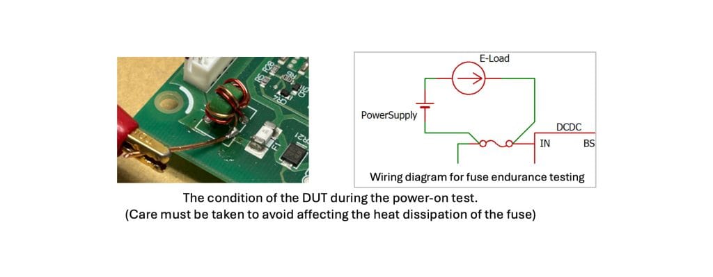
Since fuses are components that operate based on heat, it is necessary to create conditions that are as close as possible to actual operating conditions.
A power supply and electronic load are connected, and the power supply outputs a voltage (such as 5V or 10V) that ensures current flows through the fuse.
Then, the inrush current recorded using the electronic load’s sequence function can be repeatedly applied to the fuse.
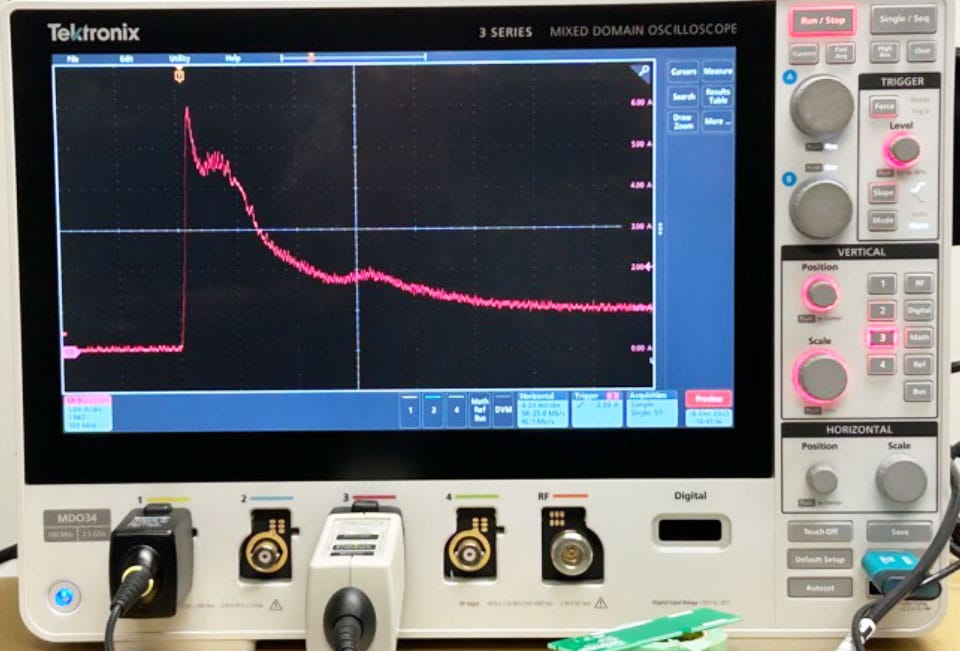
Current:1A/Div, Time scale:4ms/Div
Once you are ready to repeatedly apply the inrush current, determine the interval and number of times the inrush current will be applied, according to the expected operating conditions of the device, and then begin the test.
By counting the rising edges of the current using an oscilloscope, you can determine how many times the inrush current was applied before the fuse blew, even if you are not present at the exact moment the fuse blows.

