
What Is Hipot Testing, How Safety Analyzers Work, and How to Select the Right Model
(Kikusui TOS Series — EV, Medical, & Industrial Safety Standards)
Summary
- An Electrical Safety Tester (Hipot Tester) verifies that a product’s insulation, grounding, and leakage current are within safe limits before it reaches end users — it is the final, non-negotiable compliance gate.
- Four core tests — Hipot (AC/DC), Insulation Resistance, Ground Bond, and Leakage Current — each probe a distinct failure mode and are mandated by IEC, UL, CSA, and JIS standards.
- Choose the Kikusui TOS9311 (10 kV) for EV/PV high-voltage work, TOS9303LC for full-function R&D labs, TOS5300 for production lines, and TOS3200 or TOS9301PD for medical and partial discharge applications.
Introduction: What Is an Electrical Safety Tester?
An Electrical Safety Tester is defined as a precision metrology instrument that applies controlled high-voltage stress to a product’s insulation, verifies the physical integrity of its protective earth connections, and measures leakage currents — ensuring the product cannot cause electric shock, fire, or injury under normal or fault conditions.
In the complex journey of an electronic product from engineering concept to the consumer’s hands, the Electrical Safety Tester (also known as a Hipot Tester or Safety Analyzer) serves as the final, non-negotiable gatekeeper. While oscilloscopes and power supplies verify that a product performs its intended function, the Safety Tester verifies a far more critical attribute: that the product will not harm the user.
Electric shock, fire caused by insulation breakdown, and mechanical failure of grounding systems are catastrophic events that can lead to loss of life, massive product recalls, and irreparable brand damage. International standards bodies — IEC, UL, CSA, and JIS — mandate rigorous safety testing for virtually every electrical device, from household toasters to high-voltage EV battery packs and life-critical medical ventilators.
This guide serves as the definitive technical resource for understanding, selecting, and mastering Electrical Safety Testers. Drawing upon the advanced technology of Kikusui Electronics — from the flagship TOS9300 Series to the specialized TOS7200 Insulation Tester — we explore the physics of breakdown, compliance nuances, and advanced testing strategies for next-generation electronics.
Session 1: The Physics of Electrical Safety — The “Big 4” Tests
In short: Safety testing is a suite of four complementary tests — Hipot, Insulation Resistance, Ground Bond, and Leakage Current — each designed to detect a different failure mode that could harm a user.
Most global standards require a combination of the following four primary tests. Understanding the physics behind each is essential for proper test setup and troubleshooting.
1. Dielectric Withstand Test (Hipot Test)
Definition: The Hipot (High Potential) Test applies a high voltage (typically 1,000 V to 5,000 V, or higher for EV components) between current-carrying parts (Live/Neutral) and the non-current-carrying metal chassis (Ground) to verify the dielectric strength of the insulation.
- Goal: Stress the insulation far beyond its normal operating voltage to verify sufficient margin against transient voltage spikes (lightning, switching surges).
- Pass/Fail: If leakage current remains below the set limit (e.g., 10 mA), the device passes. If insulation fails, current spikes, causing an arc or flashover, and the tester instantly cuts power.
AC vs. DC Hipot: The Engineering Trade-off
| Factor | AC Hipot | DC Hipot |
|---|---|---|
| Polarity Stress | Alternating (+/− peaks) — mimics real AC mains stress | Single polarity — charges capacitance then reads stable leakage |
| Capacitive Loads | Reactive current causes false positives with Y-capacitors | Ideal — capacitor charges once, then current → near zero |
| Measurement | Vector sum of resistive + reactive current | Pure resistive leakage current (true defect indicator) |
| Discharge Needed | No | Yes — lethal charge in DUT must be safely drained |
| Best For | General AC-powered products | Highly capacitive loads, EV components, sensitive insulation |
2. Insulation Resistance (IR) Test
Definition: Physically similar to the DC Hipot test but performed at a lower, non-destructive voltage (typically 500 V DC or 1,000 V DC), quantifying insulation quality in Ohms (Ω) rather than delivering a simple Pass/Fail verdict.
- Hipot confirms “It didn’t break down.” IR confirms “The insulation quality is 500 MΩ.”
- Diagnostic use: Run IR before Hipot to avoid damaging a bad DUT, or after Hipot to verify that high voltage did not degrade the insulation.
3. Ground Bond (Earth Continuity) Test
Definition: A high-current test (25 A to 60 A) that verifies the safety ground pin is solidly connected to the metal chassis, ensuring any fault current can safely trip the building circuit breaker rather than electrifying the chassis.
- Why high current? Low-current continuity meters cannot burn through oxidation, rust, or lacquer on connection points. High current physically stresses the ground path to simulate a real fault.
- Pass criteria: Resistance typically < 0.1 Ω at the rated current.
4. Leakage Current (Touch Current) Test
Definition: Measures the tiny current that would flow through a human body if a person touched the device while operating, using a standardized Measuring Network (MD) that mimics human body impedance (e.g., 1 kΩ resistance with frequency-dependent filtering).
- Measured under both Normal Condition and Single Fault Conditions (Open Neutral, Open Ground).
- Critical for medical devices: A leakage of just 50 μA flowing directly to the heart via a catheter can cause ventricular fibrillation.
Session 2: Critical Technologies in Modern Safety Analyzers
In short: Modern safety analyzers use PWM amplifier architecture, rise/fall time control, and partial discharge detection to deliver stable, precise, and diagnostically rich test results that analog Variac-based testers cannot match.
2.1 PWM Amplifier Architecture: The New Standard
Traditional Hipot testers used a slide transformer (Variac) driven directly by the AC mains — if factory line voltage fluctuated, the test voltage fluctuated too.
The Kikusui Solution: The TOS9300 and TOS5300 Series utilize a high-efficiency PWM (Pulse Width Modulation) Amplifier that regenerates the high-voltage waveform internally, ensuring output is perfectly stable (±0.3%) regardless of input power quality.
- A test in a fluctuating-grid factory in Southeast Asia yields the exact same result as one in a stable European lab.
- Delivers a clean sine wave with consistent peak voltage (Vpeak = √2 × Vrms), which is critical because insulation breakdown is driven by peak voltage.
2.2 Rise Time / Fall Time Control
Applying 5,000 V instantly is physically violent for electronics — it causes massive inrush currents and voltage overshoots.
- Rise Time Control: Set a ramp-up time (0.1 s to 200 s) to linearly increase voltage, preventing false failures caused by capacitive inrush currents.
- Fall Time Control: Especially for DC testing, controlled discharge protects the DUT from reverse voltage spikes and ensures operator safety.
2.3 Partial Discharge (PD) Detection
The Phenomenon: Before insulation completely breaks down (arc), microscopic sparks called Partial Discharges can occur within gas-filled voids inside the solid insulation material. The inception conditions of these partial discharges are governed by the size of the void and the internal gas conditions; consequently, the discharge inception voltage can be evaluated based on Paschen’s Law. Over time, these micro-sparks slowly erode the insulation (a process known as “treeing”), leading to catastrophic failure months or years later.
The Solution: The TOS9301PD model measures these transient discharges. By analyzing the PDIV (Partial Discharge Inception Voltage), engineers can screen out components that pass the standard Hipot test but are destined to fail prematurely in the field — a critical capability for SiC/GaN power semiconductors and EV traction motors.
Session 3: Key Specifications Every Engineer Should Know
In short: Three specifications determine a tester’s fitness for purpose — VA rating (output capacity), current measurement resolution, and zero-cross turn-on. Verify all three before committing to a model.
3.1 VA Rating (Output Capacity)
The 500 VA Requirement: Standards like IEC 61010 require a Hipot tester to have a capacity of at least 500 VA (5,000 V @ 100 mA). If insulation breaks down, the tester must maintain voltage and drive arc current to ensure the failure is detected. A weak tester (e.g., 50 VA) might see its voltage collapse upon breakdown, potentially passing a defective unit.
- Kikusui TOS9300 and TOS5300 series meet this critical 500 VA requirement.
3.2 Current Measurement Resolution
| Application | Typical Leakage Limit | Required Resolution | Suitable Model |
|---|---|---|---|
| Industrial Motor | 10 mA | 1 mA | TOS5300 Series |
| IT Equipment (IEC 60950) | 3.5 mA | 0.1 mA | TOS9300 Series |
| Medical Device — Patient Applied (IEC 60601) | 10 μA (CF type) | 1 μA | TOS9303LC / TOS3200 |
| Cardiac Floating (Type CF) | 50 μA | 1 μA | TOS9303LC / TOS3200 |
3.3 Zero-Cross Turn-On
Function: The tester waits until the AC sine wave crosses 0 Volts before applying high voltage. Turning on at the voltage peak (90°) creates a massive transient spike. Zero-cross switching eliminates this stress, protecting the DUT during test startup.
Session 4: Kikusui TOS Series — Model Comparison and Selection
In short: Kikusui offers purpose-built models for each use case — TOS9300 for full-function R&D labs, TOS9311 for EV/PV high-voltage testing, TOS5300 for production lines, and TOS7200/TOS6210/TOS3200 for specialized single-function needs.
| Model | Key Functions | Max Voltage | Target Application |
|---|---|---|---|
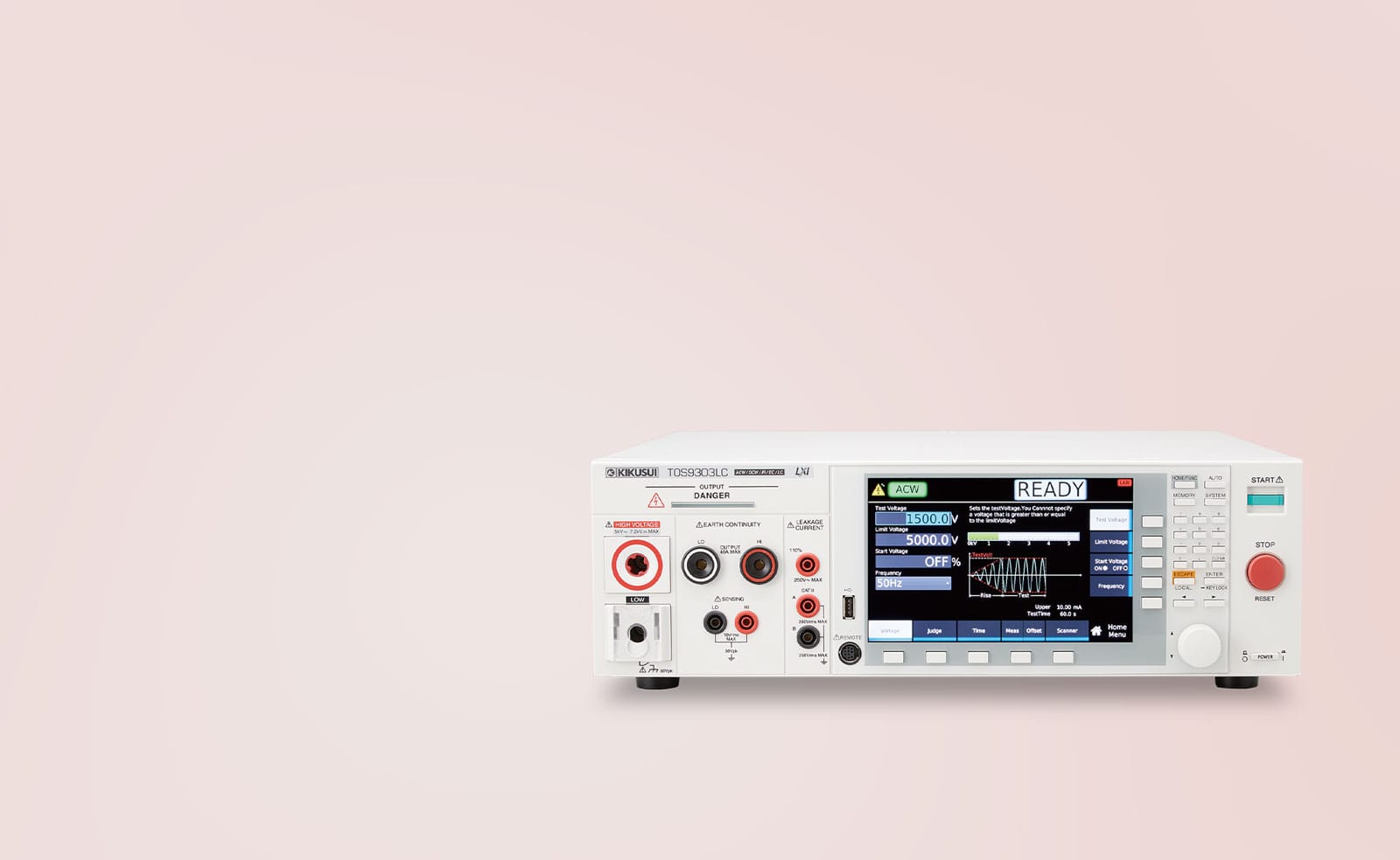
| TOS9303LC | AC Hipot, DC Hipot, IR, Ground Bond (40A), Leakage Current | DC 7.2 kV | R&D, QA, Global Compliance Labs |
| TOS9301PD | AC/DC Hipot, IR, Partial Discharge (PD) | AC 5 kV / DC 7.2 kV | EV Motors, SiC/GaN semiconductors |
| TOS9311 | AC Hipot, DC Hipot, IR | AC/DC 10 kV | EV Battery Packs, PV Inverters, HV Cables |
| TOS5300 | AC Hipot, DC Hipot, IR | AC 5 kV / DC 6 kV | Mass Production, Automated Lines |
| TOS7200 | Insulation Resistance only | 1,000 V DC | Capacitors, PCBs, Dielectric Materials |
| TOS6210 | Ground Bond only | 60 A AC | Industrial Machinery, Class-I Appliances |
| TOS3200 | Leakage Current (TC, PCC) | N/A | Medical (IEC 60601), ITE, AV Equipment |
1. TOS9300 Series — The “All-Rounder” Flagship Multi-Analyzer
Target: R&D, Quality Assurance, and Global Compliance Labs.
- Functions: AC Hipot (5 kV), DC Hipot (7.2 kV), Insulation Resistance, Ground Bond (40 A), Leakage Current, Partial Discharge.
- 7.2 kV DC Capability: Extends DC testing beyond the standard 5–6 kV ceiling, supporting next-generation solar panels and servo motors above 1,000 V without equipment upgrades.
- Universal Input (100–240 V): Deploy globally without reconfiguration.
- Lab-in-a-Box ROI: One TOS9303LC replaces four separate instruments (Hipot, IR, Ground Bond, Leakage), saving bench space, calibration costs, and simplifying automated test integration.
2. TOS9311 — The High-Voltage Specialist (10 kV)
Target: EV Battery Packs, PV Inverters, High-Voltage Cables, SiC Power Devices.
- 10 kV Output: Designed specifically for 800 V / 1,000 V EV architectures. Standards often require test voltages of 2 × Vrated + 1,000 V plus safety margin — only the TOS9311 provides this headroom.
- Offset Cancel: Measures and subtracts insulation leakage of test leads and jigs, ensuring accuracy at extreme voltages.
- DC Testing for EV: EV battery packs have massive parasitic capacitance. AC testing causes excessive reactive current and heating. The TOS9311’s DC 10 kV source allows safe, stable insulation verification of large capacitive loads.
3. TOS5300 Series — The Standard for Production Lines
Target: Mass Production, Automated Lines, Cost-Sensitive Manufacturing.
- PWM Stability: Uses the same high-stability PWM amplifier as the flagship 9300 — maintains a perfect 5,000 V regardless of factory grid fluctuations that would cause false fails on analog testers.
- Tact Time: Can perform tests as fast as 0.1 seconds, removing the bottleneck from high-volume lines (e.g., smartphone chargers).
- Physical Security: Key Lock and optional cover prevent operators from inadvertently changing test settings.
4. TOS7200 — The Insulation Resistance Specialist
Target: Electronic components (capacitors, connectors), PCBs, and dielectric materials.
- Wide Voltage Range: Variable test voltage from −25 V to −1,000 V DC with 1 V resolution — the only viable option for testing low-voltage components like MLCCs or sensitive connectors.
- Window Comparator: Sets both Upper and Lower limits. Critically, an open lead reads “Infinite Resistance” on standard testers (pass) but is flagged as FAIL on the TOS7200, preventing untested products from shipping.
5. TOS6210 — The Ground Bond Specialist
Target: Industrial Machinery, Medical Devices, Class-I Appliances.
- 60 A Capability: Many general-purpose testers cap at 30–40 A. Industrial standards (UL 60950, machinery directives) often require 60 A verification. The TOS6210 is purpose-built for this requirement.
- Constant Current: Maintains steady current even if contact resistance changes during the test, ensuring valid measurements on corroded or oxidized connections.
6. TOS3200 — The Leakage Current Specialist
Target: Medical (IEC 60601), IT Equipment (IEC 60950), AV Equipment (IEC 60065).
- 8 Built-in Measuring Networks: Pre-set impedance circuits compliant with IEC/UL standards, covering DC to 1 MHz.
- Automated Single Fault Conditions: Automatically simulates Open Neutral and Open Ground conditions — eliminating the dangerous manual rewiring that causes operator accidents.
Session 5: Application Scenarios & Real-World Validation
In short: Test requirements vary significantly by industry. EV and PV applications require 10 kV DC capability; medical requires 1 μA resolution and automated fault simulation; industrial requires 60 A ground bond.
5.1 EV Battery & Motor Insulation (UN ECE R100)
The Challenge: EV battery packs operate at 400 V to 800 V. Insulation failure can lead to thermal runaway or fatal shock to the driver or mechanic.
- DC Hipot: Use TOS9311 to apply 2,500 V DC or higher. DC voltage charges the pack’s parasitic capacitance and then monitors stable leakage current — AC testing is not viable on large capacitive loads.
- Partial Discharge: Use TOS9301PD to test the traction motor. Even a motor that passes a 3 kV Hipot test may contain micro-voids in the enamel wire caused by the inverter’s high-frequency switching (dv/dt), detectable only via PD analysis.
5.2 Medical Device Safety (IEC 60601-1, 3rd Ed.)
The Challenge: A leakage current of just 50 μA flowing directly to the heart via a catheter can cause ventricular fibrillation.
- Earth Leakage Current: Measure current from the mains part to protective earth.
- Patient Leakage Current: Measure current from the Applied Part (sensors, probes) to ground.
- Tool: TOS9303LC or TOS3200 with “Network I” (Medical MD). 1 μA resolution ensures compliance with strict Type CF (Cardiac Floating) limits.
5.3 PV (Solar) Panel Testing (IEC 61730)
Wet Leakage Current Test: The entire PV panel is submerged in a water tank (or sprayed with conductive solution), and high voltage is applied between the shorted output terminals and the water.
- Test voltage often exceeds 6,000–8,000 V for 1,500 V-rated panels. Standard 5 kV testers are insufficient.
- Tool Required: TOS9311 (10 kV model).
5.4 Industrial Control Panels (UL 508A)
The Challenge: During control panel assembly, it is critical to verify that all protective earth connections are correctly installed and provide a reliable, low-impedance path. The challenge lies in ensuring that bolted joints, contact surfaces, and grounding points have not been compromised by improper fastening or unintended insulating layers — such as paint or coatings — before the system is ever energized.
- Test: Inject 30 A or 60 A into the farthest point of the grounding system (e.g., cabinet door). Measure voltage drop to ensure resistance < 0.1 Ω.
- Tool: TOS6210 — the 60 A output ensures the ground path can safely blow the main fuse in the event of a short.
Session 6: Selection Guide, Common Mistakes, and FAQ
How to Select the Right Safety Analyzer
| Requirement | Recommended Model | Key Reason |
|---|---|---|
| Full R&D / compliance lab (all 4 tests) | TOS9303LC | All-in-one: Hipot, IR, Ground Bond, Leakage |
| EV / PV high-voltage insulation (>6 kV) | TOS9311 | 10 kV DC output with Offset Cancel |
| Motor winding / SiC partial discharge | TOS9301PD | PDIV detection below flashover threshold |
| Mass production line | TOS5300 | 0.1 s tact time, Key Lock, PWM stability |
| Capacitor / PCB / MLCC IR only | TOS7200 | 1 V resolution, Window Comparator open-lead detection |
| Industrial 60 A ground bond | TOS6210 | 60 A constant current, meets UL 60950 / machinery directives |
| Medical / ITE touch current | TOS3200 | 8 built-in networks, automated fault conditions |
Common Mistakes to Avoid
The “Floating” Mistake: Never test a DUT that is grounded elsewhere (e.g., connected to a PC via USB) without an isolation transformer. The Hipot return path might run through the USB cable and destroy the PC.
Bypassing Safety Interlocks: Shorting the interlock is the #1 cause of operator accidents. Always wire the interlock to a cage door or a dual-hand start switch.
Cable Resistance in Ground Bond Testing: At 60 A, the test leads themselves have significant resistance. Always use a 4-Wire (Kelvin) connection to cancel lead resistance and measure only the DUT.
FAQ for Engineers
Q: What is an Electrical Safety Tester and why is it required?
A: An Electrical Safety Tester (Hipot Tester or Safety Analyzer) is an instrument that verifies a product’s insulation strength, ground integrity, and leakage current before market release. It is mandated by IEC, UL, CSA, and JIS standards for virtually all electrical devices to prevent electric shock, fire, and injury.
Q: What is the difference between Flashover and Breakdown in a Hipot test?
A: Flashover is a discharge across the surface of the insulation (air arc). Breakdown is a puncture through the insulation material. Both are failures, but they indicate different design fixes — increase creepage distance (flashover) or increase insulation thickness (breakdown).
Q: My device has a Y-Capacitor and AC Hipot keeps failing. What do I do?
A: The Y-capacitor draws reactive current that the tester interprets as leakage. Two solutions: (1) Use the “Real Current” or “Offset” function on the TOS9300 to ignore the reactive component. (2) Switch to DC Hipot — DC charges the capacitor once and then reads near-zero reactive current, exposing only true insulation leakage.
Q: What is the difference between Hipot leakage current and Touch Current?
A: Hipot leakage current measures current flowing through insulation under high-voltage stress — it is a stress test. Touch Current (measured by the TOS3200 or TOS9303LC) simulates current flowing through a human body touching the product during normal operation, using a standardized body-impedance network. Only Touch Current testing is valid for medical device certification.
Q: What voltage is required to test EV battery pack insulation?
A: International standards typically require a test voltage of 2 × Vrated + 1,000 V plus a safety margin. For 800 V EV architectures, this exceeds 2,600 V and often reaches 4,000–5,000 V or higher. The Kikusui TOS9311, with its 10 kV output, provides the necessary headroom that standard 5 kV testers cannot reach.
Q: How often should I calibrate my Safety Tester?
A: Most ISO 9001 procedures require Annual Calibration. Additionally, a Daily Check using a verification box (e.g., Kikusui TOS1200) is recommended to confirm the tester can detect a failure before the shift begins.
Q: Can I test multiple points simultaneously or in sequence?
A: Yes. The TOS9320 High Voltage Scanner connects to the TOS9300 and enables programmed sequences (e.g., Pin 1 vs. Ground, then Pin 2 vs. Ground, then Pin 1 vs. Pin 2) without manual reconnection, reducing test time and eliminating operator intervention errors.
Q: What is Partial Discharge and why does it matter for EV components?
A: Partial Discharge (PD) refers to microscopic electrical sparks that occur inside voids within insulation material — below the flashover threshold but detectable via the TOS9301PD. In EV traction motors and SiC power devices, PD caused by high-frequency inverter switching (dv/dt) erodes insulation over time (“treeing”), leading to catastrophic field failure even in components that passed a standard Hipot test.
Final Thoughts: Designing for Safety, Not Just Compliance
The Electrical Safety Tester is often viewed as a final hurdle on the production line, but its value extends far upstream. By utilizing advanced capabilities like Partial Discharge detection and high-resolution leakage analysis during the R&D phase, engineers can identify weak insulation designs long before they become field failures.
Kikusui Electronics’ TOS Series represents the culmination of over 70 years of safety testing expertise. Whether you need the rugged speed of the TOS5300 for the factory floor, the analytical depth of the TOS9300 for the lab, or the extreme voltage of the TOS9311 for the electric future, Kikusui’s instruments ensure that when your product powers up, it does so safely.

