We use a bridge to double output voltage
Series Output from Bipolar Power Supplies
In this article I will discuss applications for the PBZ series bipolar power supply. One question I get asked a lot about the PBZ series is whether multiple units can be linked in series. The engineer in me is ashamed to have to tell my clients, “unfortunately, no”. However, while referred to as “power supplies”, the PBZ series are effectively a range of power amplifiers. I tried to come up with an elegant solution for boosting their power output. (Readers who are familiar with audio equipment might be able to tell where I’m going with this.)
Some stereo audio amplifiers have what is known as a “BTL switch”. Flicking this switch connects the left channel amplifier and right channel amplifier together by a bridge, enabling the device to function as a single, monaural amplifier. (Figure 1) BTL stands for “bridge-tied load” or “bridged transformer-less”. Incidentally, the photo at the top in this article is a BLT Burger…
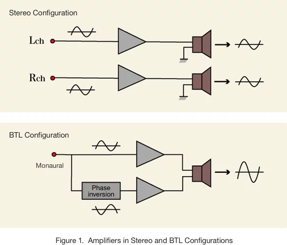
Theoretically, if we take the BTL configuration in Figure 1 and replace the amplifier with one from the PBZ series and the speaker with the device under test, the circuit should be able to be used in the same way. While the two power supplies are not connected in series in the strict sense of the phrase, this configuration does enable us to double (amplify) the output voltage. In this article, I will describe how to connect the circuit and provide some notes on use.
Setting up the System
As illustrated in Figure 2, the output is taken from the output terminals of the respective power supplies. Note that the system can only be earthed via the COM terminal. While the frequency response does drop to around 50% (50kHz) in constant voltage mode─80% (8GHz) in constant current mode, the circuit is still quite suitable as a high-speed bipolar power supply.
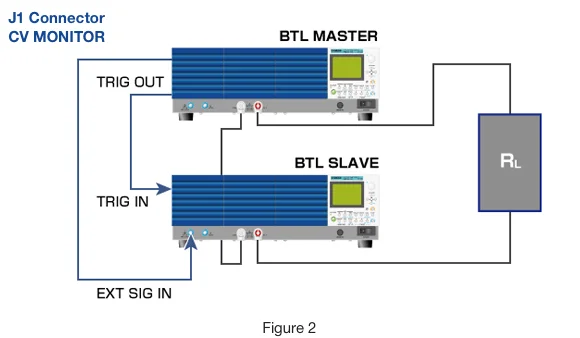
The principle of operation is that the BTL Master in the diagram (“Master Unit”) makes the BTL slave (“Slave Unit”) output a voltage (V-) that is opposite in phase from the output of the Master Unit (V+). The output voltage is taken from the output terminal of the Master Unit and the output terminal of the Slave Unit. The output voltage arising across RL is double the voltage that would be generated by a single unit.
Connecting the Units
1. Connect the COM terminal of the Master Unit to the COM terminal of the Slave Unit.
2. Connect the OUTPUT terminals of the two power supplies to RL.
3. Make sure that the OUTPUT terminals on rear of the units are not grounded. The COM terminals on the rear of the units may be grounded if desired.
4. Connect the CV MONITOR output J1 connector on the rear of the Master Unit (13,18) to EXT SIG IN on the front panel of the Slave Unit.
5. Synchronize the units using the trigger by connecting TRIG OUT on the rear of the Master Unit to TRIG IN on the rear of the Slave Unit.
Configuration
Once the units have been connected as shown Figure 1, it is time to configure them. Specifically, we need to configure synchronization and external signal input (external voltage control). I recommend pressing “shift” while turning on the power to restore all settings to factory presets.
Configuring the Master Unit
So that the toggling of the OUTPUT ON/OFF switch on the Master Unit will cause the Slave Unit’s OUTPUT ON/OFF to be toggled as well, configure SYNCHRONOUS>OPERATION {CONFIG[3] (3/7)} as described below. (Refer to page 89 of the instruction manual.)
1. Repeatedly press CONFIG until you reach 3/7.
2. Use the controls to set SYNCHRONOUS>OPERATION to “MASTER”.
3. The settings take effect the moment the display switches to “MASTER”.
Configuring the Slave Unit
Step1.
So that the OUTPUT ON/OFF of the Slave Unit operates in sync with the OUTPUT ON/OFF switch of the Master Unit, configure SYNCHRONOUS>OPERATION {CONFIG[3] (3/7)} as described below. (Refer to page 89 of the instruction manual.)
1. Repeatedly press CONFIG until you reach 3/7.
2. Use the controls to set SYNCHRONOUS>OPERATION to “SLAVE”.
3. The settings take effect the moment the display switches to “SLAVE”.
Step2.
The Slave Unit will now operate in sync with the output voltage of the Master Unit, so rather than using the Slave Unit’s internal signal source, we connect the Master Unit’s CV monitor to the EXT SIG IN input on the front panel of the Slave Unit to provide an external signal. We therefore configure (2/7) SIGNAL SOURCE>SELECT as described below. (Refer to page 88 of the instruction manual)
1. Repeatedly press CONFIG until you reach 2/7.
2. Use the controls to set SIGNAL SOURCE>SELECT to “EXT”.
3. Use the controls to set SIGNAL SOURCE>EXT SELECT to “BNC”.
4. The settings take effect the moment the display switches to “BNC”.
Step3.
So that the output voltage of the Slave Unit will be negative in comparison to the output voltage of the Master Unit, we configure external signal circuit gain and output polarity as described below. We therefore configure SIGNAL SOURCE>EXT GAIN {CONFIG[2] (2/7)} as described below. (Refer to page 88 of the instruction manual.)
1. repeatedly press CONFIG until you reach 2/7.
2. use the controls to set SIGNAL SOURCE>GAIN as described below. By entering a negative value we can switch the polarity.
· PBZ20: -10.00
· PBZ40: -20.0
· PBZ60: -30.0
· PBZ80: -40.0
3. The settings take effect the moment the display switches to the new value.
4. The gain adjustment referred to in step 2 is used to precisely match the inverted voltage of the Slave Unit to the voltage output by the Master Unit.
Using the System
- OUTPUT ON/OFF can only be toggled on the Master unit.
- CV (continuous voltage), CC (continuous current), and maximum current settings are all performed on the Master Unit.
- If two identical power supplies are used, the voltage output will be double that configured on the Master Unit.
- The Slave Unit’s response time should be set to the minimum value.
- Signal control can be performed via the Master Unit.
Output Response
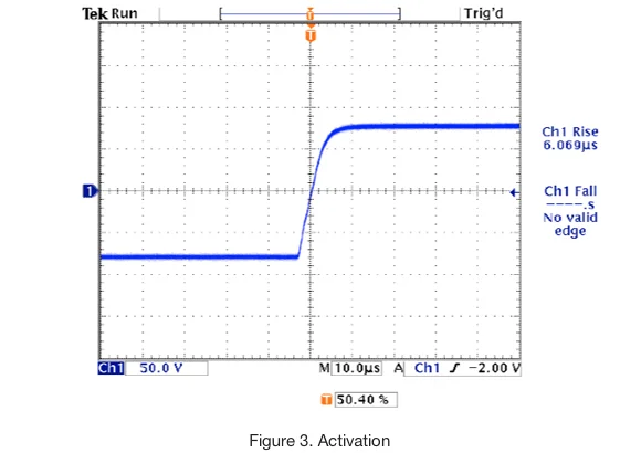
The output waveform generated by the two PBZ40-10 units are shown below.
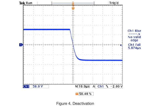
The system’s rise and fall response at constant voltage is shown in Figure 3 and 4.
PBZ40-10
RESPONSE
MASTER: 3.5us(CV)
SLAVE: 3.5us(CV)
AC 40Vpp DC 0V
RL=8Ω
SLAVE EXTGAIN: -20
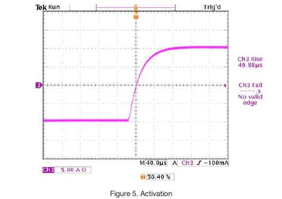
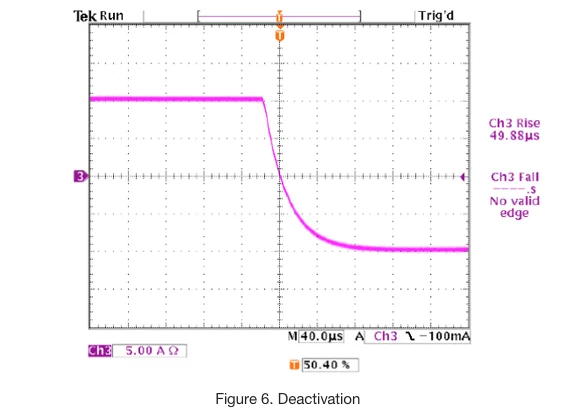
The system’s rise and fall response at constant current is shown in Figure 5 and 6.
PBZ40-10
RESPONSE
MASTER: 70us(CC)
SLAVE: 3.5us(CV)
AC 20Vpp DC 0A
RL=8Ω
SLAVE EXTGAIN: -20
Other Notes on Use
Combining Two Different Devices
The PBZ units used may have the same or differing rated voltages, but when units with different rated voltage are combined, the output voltage of the Slave Unit will be set in accordance with this differential, so the total voltage output will not increase by a factor of two. For example, when combining a PBZ40 Master Unit with a PBZ20 Slave Unit and setting the PBZ40 output voltage to 20V, the output voltage of the PBZ20 will be 10V, and the voltage supplied to the load will be 30V.
Caution Regarding Measurement
When using an oscilloscope to measure the output voltage of the system, be sure to use a differential probe. If you do not, the probe may short the output from the PBZ, destroying the probe.
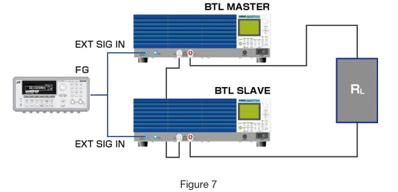
Obtaining Frequency Profile of CV 100kHz
We used a standard BTL amplifier as illustrated in Figure 7. We use a function generator (FG) to apply the desired voltage to the EXT SIG IN terminal and set GAIN to a negative value to switch the polarity. In order to synchronize powering up and down between the two units, we connected their synchronization triggers together. This system can also only be earthed via the COM terminal.